background image

Change Sample Racks

The system is provided with 1.5 mL sample vial plates as a standard. This section provides the procedure for
changing the settings to use other plates.

Set the Rack ID

The rack ID is the ID the module uses to identify the type of plate that has been inserted. Set the rack ID by operating
the sliding switch at the rear of the sample rack.

The two sample racks provided with the module have rack IDs set to A and B by default, which means that the
needle strokes and rack positions are adjusted for a 1.5 mL sample vial plate.

Note: 

If the rack ID settings have been changed, then it is necessary to configure the plate type, set the needle

stroke from the top, and then adjust the rack position. Refer to the 

ExionLC

TM

 100 System Hardware User

Guide

 for instructions.

Note: 

If the plate type is changed but the same rack ID is used, then the needle stroke from the top should be

set and the rack position adjusted.

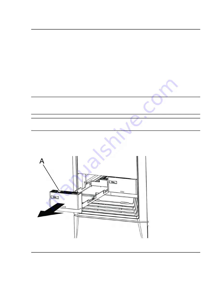
1. Remove the sample rack (A).

Figure 5-23 Sample Rack Removal

Hardware User Guide

ExionLC

 100 System

RUO-IDV-05-1839-C

124 / 219

Service and Maintenance

Summary of Contents for ExionLC 100

Page 1: ...ExionLC 100 System Hardware User Guide May 2018 RUO IDV 05 1839 C...

Page 2: ...and does not imply any right and or license to use or permit others to use such manufacturers and or their product names as trademarks SCIEX warranties are limited to those express warranties provided...

Page 3: ...Adjustment 17 Storage and Handling 18 2 Overview 19 Front Side 20 Side View 22 Rear Panels 24 Interior View 25 Flow Line Diagram 27 Entire Flow Line 27 Inner Volume of Each Flow Line 28 Flow Line Dur...

Page 4: ...al of Sample Racks During Analysis 101 Post Analysis Procedures 102 Rinse the Flow Line 102 Turn Off the System 102 5 Service and Maintenance 104 Replace the Mobile Phase 105 Replace the Mobile Phase...

Page 5: ...and Spares 184 Consumables 184 Sample Vials for Use with the Autosampler 185 Septum for Use with the Autosampler 188 Microtiter Plate 189 Pump Spares 191 Autosampler Spares 192 Column Oven Spares 193...

Page 6: ...FSE for repairs that require the covers to be removed Follow required electrical safe work practices Use cable management practices to control electrical cables This will reduce the chance of a tripp...

Page 7: ...rrupt the protective earth conductor Any interruption of the protective earth conductor creates an electrical shock hazard Environmental Precautions Use qualified personnel for the installation of ele...

Page 8: ...ause a wrong result Make sure that a compatible electromagnetic environment for the equipment can be maintained so that the device will perform as intended Decommissioning and Disposal Before decommis...

Page 9: ...o cleaning or maintenance if radioactive materials biological agents or toxic chemicals have been used with the system WARNING Environmental Hazard Do not dispose of system components in municipal was...

Page 10: ...nded Use secondary containment trays beneath the solvent bottles and the waste collection container to capture potential chemical spills System Safe Fluids The following fluids can safely be used with...

Page 11: ...tive measures for static electricity can be difficult because the symptoms before an accident vary and can be hard to detect because such accidents occur as a result of several simultaneous incidents...

Page 12: ...er a Solid Description Item Flowing liquid 1 Solid 2 Charges move with the flow of liquid 3 Immobile charges fixed to the surface of the solid 4 Generation of static activity If electrostatically char...

Page 13: ...1 2 Potential Accident Situation Description Item Dry air 1 Spark 2 Liquid flowing through thin tubing at a high rate Air bubbles in liquid facilitate generation of static electricity 3 Insulated cont...

Page 14: ...humidity level Ambient humidity exceeding 65 will prevent static Note For low conductivity less than 10 10 S m liquids take preventive measures 1 to 4 For these liquids preventive measure 5 has no ef...

Page 15: ...ective earth then static electricity can build up in the container CAUTION Potential System Damage Do not connect the grounding wire to the gas tubing the water service tubing or the telephone line No...

Page 16: ...e Preventive Measure Four Use tubing with an inner diameter of at least 2 mm for drain lines with high flow rates Guidelines Periodically inspect the tubing connections for leaks Air bubbles in liquid...

Page 17: ...twear when moving heavy objects Maintenance Inspections and Adjustment WARNING Personal Injury Hazard Contact the SCIEX representative if product installation adjustment or relocation is required WARN...

Page 18: ...not exceed 2 C 3 6 F per hour Ambient temperature fluctuations exceeding these limits will result in higher signal drift and an inconsistent baseline signal from the detector For ambient temperatures...

Page 19: ...of each unit of the pump autosampler and column oven for executing control The network function included as standard enables monitoring of the analysis status from the acquisition computer CAUTION Pot...

Page 20: ...Description Item Controller 1 Autosampler 2 Pump 3 Column oven 4 Front Side Figure 2 2 Front Side Hardware User Guide ExionLC 100 System RUO IDV 05 1839 C 20 219 Overview...

Page 21: ...ransparent panel that enables inspection of an installed sample If the front panel is removed the parts of the autosampler such as a needle and high pressure valve can be maintained 2 Sample rack Hold...

Page 22: ...n filter is attached to the end 1 Reservoir bottle Contains the mobile phase or the rinse solution for the autosampler 2 Reservoir tray Contains reservoir bottles and seal rinse bottles 3 Optional Aut...

Page 23: ...the controller The power can be turned on and off from the front side of the system using the power button of the controller if the main power switch is turned on When the system will not be used for...

Page 24: ...al part 1 RS232C connector Unused 2 ETHERNET connector Connects the acquisition computer 3 External input output terminal Connects external devices including the mass spectrometer and synchronizes usi...

Page 25: ...erature of the column is maintained at a given value 1 High pressure valve Switches between high pressure flow lines 2 Low pressure valve Switches between the sample liquid and the rinse solution for...

Page 26: ...stabilizes the baseline 5 Pump Pumps the mobile phase 6 Drain valve Opens the discharge flow line during a manual purge 7 Low pressure gradient unit Mixes a maximum of four types of mobile phases 8 D...

Page 27: ...ram Entire Flow Line Figure 2 6 Entire Flow Line Description Legend Low pressure mobile phase High pressure mobile phase Flow line direction ExionLC 100 System Hardware User Guide 27 219 RUO IDV 05 18...

Page 28: ...the system delay volume by replacing 40 L LPGEOUT tube volume with 315 L Example 275 315 40 30 230 35 925 L 5 If trifluoroacetic acid TFA fis being used or the mobile phase then use Mixer MR300 L prov...

Page 29: ...Operations Sample injection operations occur in the following order Ready The mobile phase sent from the pump goes through the high pressure valve sample loop needle injection port then back to the h...

Page 30: ...em Low Pressure Valve 8 Pump 1 Measuring Pump 9 High Pressure Valve 2 Rinsing Port 10 Sample Loop 3 Drain Waste Rinse Liquid 11 Needle 4 Sample 12 Injection Port 5 Manual Prime Port 13 Column 6 Rinse...

Page 31: ...in the sample loop Figure 2 8 Flow Line Description Legend Mobile phase Release of pressure Flow line direction Description Item Description Item Low Pressure Valve 8 Pump 1 Measuring Pump 9 High Pres...

Page 32: ...ion Port 5 Manual Prime Port 13 Column 6 Rinse Solution 7 Needle Movement After the low pressure valve has operated the needle moves up Figure 2 9 Needle Movement Description Legend Mobile phase Flow...

Page 33: ...2 Injection Port 5 Manual Prime Port 13 Column 6 Rinse Solution 7 Needle Rinse Before Sample Aspiration The needle is inserted in the rinse port and the outside of the needle is rinsed with rinse solu...

Page 34: ...em Low Pressure Valve 8 Pump 1 Measuring Pump 9 High Pressure Valve 2 Rinsing Port 10 Sample Loop 3 Drain Waste Rinse Liquid 11 Needle 4 Sample 12 Injection Port 5 Manual Prime Port 13 Column 6 Rinse...

Page 35: ...in the needle and the sample loop Figure 2 11 Flow Line Description Legend Mobile phase Aspiration Flow line direction Description Item Description Item Low Pressure Valve 8 Pump 1 Measuring Pump 9 H...

Page 36: ...le Rinse After Sample Aspiration The needle is inserted in the rinsing port and the outside of the needle is rinsed with rinse solution in the rinsing port This rinse step can be omitted if required F...

Page 37: ...t 5 Manual Prime Port 13 Column 6 Rinse Solution 7 Start Analysis When the needle is inserted in the injection port the high pressure valve shifts to the injecting position and analysis starts Along w...

Page 38: ...em Low Pressure Valve 8 Pump 1 Measuring Pump 9 High Pressure Valve 2 Rinsing Port 10 Sample Loop 3 Drain Waste Rinse Liquid 11 Needle 4 Sample 12 Injection Port 5 Manual Prime Port 13 Column 6 Rinse...

Page 39: ...on Figure 2 14 Mobile Phase Description Legend Mobile phase Flow line direction Description Item Description Item Low Pressure Valve 8 Pump 1 Measuring Pump 9 High Pressure Valve 2 Rinsing Port 10 Sam...

Page 40: ...lution Aspiration When the needle is inserted in the sample vial the measuring pump is activated and the sample is aspirated in the needle and the sample loop Figure 2 15 Flow Line Description Legend...

Page 41: ...Waste Rinse Liquid 11 Needle 4 Sample 12 Injection Port 5 Manual Prime Port 13 Column 6 Rinse Solution 7 Rinse Solution Discharge After the low pressure valve has operated the measuring pump discharge...

Page 42: ...on Item Low Pressure Valve 8 Pump 1 Measuring Pump 9 High Pressure Valve 2 Rinsing Port 10 Sample Loop 3 Drain Waste Rinse Liquid 11 Needle 4 Sample 12 Injection Port 5 Manual Prime Port 13 Column 6 R...

Page 43: ...er Guide Some system configuration tasks can be performed with the touch pad on the controller Configure Initial Settings Show the Calibration Tab 1 Press Menu Figure 3 1 Menu Button The Menu screen i...

Page 44: ...2 Press Maintenance Figure 3 2 Maintenance Button The Maintenance screen is shown 3 Press Calibration Hardware User Guide ExionLC 100 System RUO IDV 05 1839 C 44 219 Configuration...

Page 45: ...The Login screen is shown 4 Type the system pass ID number in the Password field The factory default pass ID is 00000 Figure 3 4 Login Screen 5 Press OK ExionLC 100 System Hardware User Guide 45 219 R...

Page 46: ...m Shows the Parts Replacement Reference Values Setting screen is screen allows the settings for parts replacement time guidelines to be configured Parts Replacement Reference Values 1 Shows the Valida...

Page 47: ...creen This screen allows the login pass ID Number that is required to log on to the module to be changed Refer to Change the Login Pass ID Login PassID Setting 6 Shows the Initialization Instrument Pa...

Page 48: ...uttons for validation items are shown on the tab of each unit The criteria for the applicable validation can be set by pressing this button Figure 3 7 Validation Acceptance Criteria Values Setting Scr...

Page 49: ...s the hardware calibration status for the specific unit Unit Selection Tab 2 Hardware Calibration Operations Screen Use this screen to perform hardware calibration Follow the instructions shown on the...

Page 50: ...op Returns to the previous step Back Proceed to the next procedure Next Shows when the results are given after all the procedures are finished Closes the screen Finish Shows the current step in light...

Page 51: ...assword Input screen is shown at the time of operation to prohibit screen operation unless the login password is input Key Lock 3 Shows the Network Setting screen The network settings can be configure...

Page 52: ...he analysis is registered Refer to Set Password Request to Deactivate the Lock Password request to deactivate lock 8 Set a Safety Lock Prerequisite Procedures Show the Calibration Tab A safety lock ca...

Page 53: ...reen is shown 2 Press Safety Lock Figure 3 12 Safety Lock Button The Safety Lock screen is shown 3 Press the switching button and then select Set ExionLC 100 System Hardware User Guide 53 219 RUO IDV...

Page 54: ...Show the Calibration Tab Set whether to show the Login screen when the system starts the lock is canceled with the Lock deactivating button or the Upload screen is shown with the Upload button 1 Pres...

Page 55: ...Figure 3 14 System Adjustment Button The System Adjustment screen is shown 2 Press Password request to deactivate lock ExionLC 100 System Hardware User Guide 55 219 RUO IDV 05 1839 C Configuration...

Page 56: ...rd request to deactivate lock Button The Password request to deactivate lock screen is shown 3 Press the switching button and select Enabled Hardware User Guide ExionLC 100 System RUO IDV 05 1839 C 56...

Page 57: ...ure 3 16 Enabled Button Configure Network Settings Prerequisite Procedures Show the Calibration Tab 1 Press System Adjustment ExionLC 100 System Hardware User Guide 57 219 RUO IDV 05 1839 C Configurat...

Page 58: ...Figure 3 17 System Adjustment Button The System Adjustment screen is shown 2 Press Network Setting Hardware User Guide ExionLC 100 System RUO IDV 05 1839 C 58 219 Configuration...

Page 59: ...Figure 3 18 Network Setting Button The Network Setting screen is shown 3 Configure the network settings ExionLC 100 System Hardware User Guide 59 219 RUO IDV 05 1839 C Configuration...

Page 60: ...Figure 3 19 Network Settings Screen Page 1 Figure 3 20 Network Settings Screen Page 2 Hardware User Guide ExionLC 100 System RUO IDV 05 1839 C 60 219 Configuration...

Page 61: ...manually input IP Address Subnet mask and Default Gateway IP Address Setting Note If the IP address is allocated from a DHCP server if automatic acquisition is selected then make sure that the term o...

Page 62: ...Figure 3 21 System Adjustment Button The System Adjustment screen is shown 2 Press Date Setting Hardware User Guide ExionLC 100 System RUO IDV 05 1839 C 62 219 Configuration...

Page 63: ...en Description Field Input the date in the Western format Date Input the time using the 24 hour clock system Time Specify the order of date components For example December 31 2013 is shown as follows...

Page 64: ...ibration Tab 1 Press System PassID Setting Figure 3 23 System PassID Setting Button The System PassID Setting screen is shown 2 Press and then type a new 5 digit system pass ID Number Hardware User Gu...

Page 65: ...n The message follwing message is shown Again for confirmation enter the system pass ID Number 3 Press type the new system pass ID Number again and then press OK ExionLC 100 System Hardware User Guide...

Page 66: ...em pass ID Number fails this message is shown The system pass ID Numberentered does not match the one for verification purposes Please change the system pass ID Number again 4 Press Close Change the L...

Page 67: ...26 Login PassID Setting Button The Login PassID Setting screen is shown 2 Press and then type a new 5 digit login pass ID Number ExionLC 100 System Hardware User Guide 67 219 RUO IDV 05 1839 C Config...

Page 68: ...ing Screen The message Again for confirmation enter the login pass ID Number is shown 3 Press type the new login pass ID Number again and then press OK Hardware User Guide ExionLC 100 System RUO IDV 0...

Page 69: ...ification purposes Please change the login pass ID Number again 4 Press Close Initialize Settings Prerequisite Procedures Show the Calibration Tab The parameters of parameter settings and system setti...

Page 70: ...Press Initialization Figure 3 29 Initialization Button The Initialization Instrument Parameters screen is shown 2 Press OK Hardware User Guide ExionLC 100 System RUO IDV 05 1839 C 70 219 Configuratio...

Page 71: ...off Configure the System to Shut Down after Analysis Shutdown can be configured so that the system terminates automatically after analysis completion It is possible to change the oven temperature and...

Page 72: ...Figure 3 31 Menu Button The Menu screen is shown 2 Press Shutdown Hardware User Guide ExionLC 100 System RUO IDV 05 1839 C 72 219 Configuration...

Page 73: ...Figure 3 32 Shutdown Button The Shutdown Setting screen is shown 3 Set Shutdown to ON ExionLC 100 System Hardware User Guide 73 219 RUO IDV 05 1839 C Configuration...

Page 74: ...nge the setting contents press anywhere in the content area of the shutdown file No The Edit Shutdown File screen is shown 6 Set the unit parameters after the completion of the analysis Hardware User...

Page 75: ...tep Prepare the Mobile Phase and Rinse Solution Prepare the mobile phase and rinse solution for the autosampler 1 Install the Column Prepare the column 2 Turn on the HPLC System and Log on to the HPLC...

Page 76: ...turning it on A login pass ID Number is required on the Start screen The initial value is 00000 To change the value refer to Change the Login Pass ID 1 Make sure that the mains supply cable is connec...

Page 77: ...ber is 0000 To change the login password refer to Change the Login Pass ID 2 Press OK The Main Analysis screen opens Prepare the Mobile Phase and Rinse Solution WARNING Biohazard Toxic Chemical Hazard...

Page 78: ...for analysis then purge the mobile phase or rinse solution from the flow line with distilled water or other liquid that is less corrosive Also turn off the autosampler after analysis and open the fron...

Page 79: ...n all of the flow lines thoroughly with HPLC grade water immediately after analysis Halogen ions can corrode the stainless steel material SUS316L Avoid ammonia aqueous solution at a concentration exce...

Page 80: ...a concentration exceeding 1 TFA solution at a concentration exceeding 0 1 After the analysis finishes replace the rinse solution with a liquid that does not contain acid such as HPLC grade water or me...

Page 81: ...r injection of the sample flow lines indicated by solid lines in are filled with rinse solution Flow lines indicated by dashed lines are filled with mobile phase Figure 4 2 Rinse Step A Description It...

Page 82: ...f mobile phase compressed by high pressure is pushed through the high pressure valve ports 1 and 2 Depending on the pumping pressure rinse solution and the mobile phase might be mixed in the area insi...

Page 83: ...lvent might cause the check valve on the pump inlet side to malfunction and reduce retention time reproducibility Example Guideline for relevant buffer solutions Potassium phosphate buffer solution at...

Page 84: ...sion Refer to Replace the Mobile Phase 1 Prepare a mobile phase and then put it into a dedicated reservoir bottle Tip SCIEX recommends that the mobile phase be filtered it through a membrane filter wi...

Page 85: ...utopurge The mobile phase ports and the rinsing port of the autosampler are automatically purged Fill the whole flow line with mobile phase before installing the column Purge mobile phase ports that a...

Page 86: ...ampler might flow in the column and precipitate salt To replace a mobile phase after using a buffer solution rinse the column with a liquid that does not form a precipitate in the buffer solution such...

Page 87: ...for rinse solutions If air bubbles are found in the flow line set the time two to five minutes longer than the initial value If air bubbles remain in the flow line despite a longer purge time then op...

Page 88: ...currently being purged and start purging of the next mobile phase For another operation press Close The Running screen closes but the purge continues To show the Running screen press Purge on the Mai...

Page 89: ...e 4 8 Purging In Process 5 After the purge finishes press Close The Main Analysis screen opens Figure 4 9 Close Button ExionLC 100 System Hardware User Guide 89 219 RUO IDV 05 1839 C Operating Instruc...

Page 90: ...ettings only when the pumping mode is set to GRAD Warm up Pumps the mobile phase at half the initial flow rate with the initial GRAD settings After the warming up time finishes the flow rate returns t...

Page 91: ...al UHPLC fitting 1 Open the column oven door Figure 4 11 Opening the Column Oven Door 2 Attach the column A to the column clamps B with the outlet side a turned up ExionLC 100 System Hardware User Gui...

Page 92: ...he column Connect the SUS tubing B to the inlet side a of the column A from the autosampler Note For the fittings to be used refer to Consumables Options and Spares Hardware User Guide ExionLC 100 Sys...

Page 93: ...e door Attach Multiple Columns Installing optional column clamps allows multiple columns to be attached Tip Installing the optional FCV 14AH valve allows automatic switching of multiple columns 1 Inst...

Page 94: ...Figure 4 14 Columns from 100 mm to 300 mm Hardware User Guide ExionLC 100 System RUO IDV 05 1839 C 94 219 Operating Instructions...

Page 95: ...ror due to pressure that is too high or it might damage the column Pump at a lower flow rate until the oven temperature reaches the set value 2 Press Pump and Oven Pump and Oven are illuminated in blu...

Page 96: ...ator and rotor of the high pressure valve resulting in liquid leakage in a short period of time CAUTION Potential System Damage Dilute high viscosity samples before use High viscosity samples might no...

Page 97: ...sample solvent might melt the silicone rubber CAUTION Potential System Damage Use an appropriate septum If the septum is not suitable for use then the flow line might become clogged with septum shavin...

Page 98: ...ed down Figure 4 17 Sample Vial Note When the sample is cooled the liquid level should be as indicated in the following Figure 4 18 If it is higher then the sample might not be sufficiently cooled Fig...

Page 99: ...ired settings Note The autosampler is provided with 1 5 mL sample vial plates by default When using other plates be sure to adjust the rack ID settings needle stroke settings and rack positions Refer...

Page 100: ...erted then the needle might pierce the wrong position and damage the instrument or become clogged In addition the needle might pierce the cap for the sample upon sample aspiration and cause an error 3...

Page 101: ...in damage to the needle During injection the rack LED of the sample rack with the plate injected with the sample will flash When the LED for a rack A is not flashing the sample rack can be removed eve...

Page 102: ...r cases when water is used for the mobile phase for analysis including reversed phases and ion exchanges Rinse the entire flow line with HPLC grade water and then rinse with methanol For cases when wa...

Page 103: ...e corruption of the settings data The Confirmation screen opens 2 Press OK 3 Make sure that the power button is orange 4 Turn off the main power switch 5 Disconnect the mains supply cable at the rear...

Page 104: ...gents in order to prevent contact with the skin WARNING Hot Surface Hazard Do not open the column oven door if the high temperature lamp is blinking The internal temperature of the column oven is 60 C...

Page 105: ...eplaced or Mixed Directly Recommended Action Possible Problem Solvent Combination Replace the solvent with isopropanol Emulsion and separation Water and mobile phase with a low dielectric constant hex...

Page 106: ...e fifth of the analysis flow rate Flow Rate Setting 5 Press Pump to start pumping The liquid in the column is replaced with column sealing liquid After the liquid is replaced the pressure becomes stab...

Page 107: ...obile phase into a 200 mL beaker 2 Remove the suction filter from the reservoir and then put the filter into the beaker filled with the new mobile phase in the preceding step Figure 5 3 Replace the Mo...

Page 108: ...ockwise to open the drain valve Refer to Figure 5 4 Figure 5 4 Open the Drain Valve Description Item Open counter clockwise 1 Drain valve knob 2 Note If the drain valve knob is turned more than 180 de...

Page 109: ...alve knob 1 Drain tubing to waste bottle 2 8 Disconnect the tubing connecting autosampler outlet to the column and then put the tubing into the waste container Figure 5 6 Tubing Configuration ExionLC...

Page 110: ...e is set to a value that maintains the pressure at a setting that is lower than the maximum column pressure Precautions when Replacing the Mobile Phase Replace a Liquid with a Non Miscible Solvent Req...

Page 111: ...matically rinses the plunger and plunger seal of the pump Select a rinse liquid to use for rinsing as follows If water is used for the mobile phase including reversed phases and ion exchanges then use...

Page 112: ...cap B from the rinse solution bottle A in the automatic rinsing kit and add then 1 L of 1 9 isopropanol HPLC grade water Figure 5 9 Rinse Bottle Cap Removal Hardware User Guide ExionLC 100 System RUO...

Page 113: ...ions 4 Attach the syringe needle C to the end of the FEP tubing E in the upward U shape and then use the syringe D to suction the 10 isopropanol solution out from the rinse flow line 5 Remove the syri...

Page 114: ...ton Turn on Pump Pump is illuminated in blue and pumping starts 8 Make sure that the rinse liquid flows from the end of the FEP tube on the outlet side of the automatic rinsing kit Hardware User Guide...

Page 115: ...f purging with autopurge is not sufficient or if there is no liquid in the suction tubing then purge manually with a syringe 1 Put the suction tubing to be purged in a reservoir bottle to which a mobi...

Page 116: ...reful not to pinch fingers when opening or closing the doors 3 Open the pump door rotate the drain valve knob A 90 degrees counter clockwise and then open the drain valve Hardware User Guide ExionLC 1...

Page 117: ...Figure 5 15 Drain Valve 4 Configure the pump settings Figure 5 16 Pump Settings ExionLC 100 System Hardware User Guide 117 219 RUO IDV 05 1839 C Service and Maintenance...

Page 118: ...e in Process 6 Inject the mobile phase with the syringe The criterion value for the aspirated volume is 10 mL 7 When purge another mobile phase port change the mobile phase ports in the Main Analysis...

Page 119: ...bes downstream from the pump perform autopurging for 3 minutes or more for all of the mobile phase ports for which manual purging was performed until there are no air bubbles in the flow line Prime th...

Page 120: ...te rinse solution and then replace with the required solvent 1 Open the valve mount door Figure 5 19 Valve Mount Door 2 Insert the syringe with a needle A into the tube coming out of low pressure valv...

Page 121: ...Figure 5 20 Syringe Installed 3 Press Purge on the Main Analysis screen ExionLC 100 System Hardware User Guide 121 219 RUO IDV 05 1839 C Service and Maintenance...

Page 122: ...Figure 5 21 Purge Button The Auto Purge screen is shown 4 Press Manual Prime Hardware User Guide ExionLC 100 System RUO IDV 05 1839 C 122 219 Service and Maintenance...

Page 123: ...een is shown 7 Reset the tube and close the valve mount door 8 Configure the settings for Rinse to 10 minutes or more and then perform an autopurge Refer to Perform an Autopurge Note After manual prim...

Page 124: ...efault which means that the needle strokes and rack positions are adjusted for a 1 5 mL sample vial plate Note If the rack ID settings have been changed then it is necessary to configure the plate typ...

Page 125: ...ple rack Note Move the sliding switch forward or backward after pushing the projection a little Note Set different rack IDs for the left and right sample racks If the same rack ID is set this error me...

Page 126: ...Figure 5 25 Rack ID Table Seven different rack types can be selected A to G Hardware User Guide ExionLC 100 System RUO IDV 05 1839 C 126 219 Service and Maintenance...

Page 127: ...Table 5 4 Rack Types Sliding Switch Position Rack ID A B C ExionLC 100 System Hardware User Guide 127 219 RUO IDV 05 1839 C Service and Maintenance...

Page 128: ...Table 5 4 Rack Types continued Sliding Switch Position Rack ID D E Hardware User Guide ExionLC 100 System RUO IDV 05 1839 C 128 219 Service and Maintenance...

Page 129: ...fix to the Front of the Handle The sample rack is supplied with labels to be put on the handle When necessary apply them to a location that can be easily seen such as the front of the handle ExionLC 1...

Page 130: ...the needle might strike the plate instead of descending into the well resulting in damage to the needle Note The provided sample rack holds a 1 5 mL sample vial plate 1 Insert the provided plate iden...

Page 131: ...te Front 4 mL 4 mL sample vial plate Back MTP96 96 Well microtiter plate Back DWP96 96 Well deep well plate Back MTP384 384 Well microtiter plate Back DWP384 384 Well deep well plate Tip Flip the pane...

Page 132: ...Figure 5 28 Panel Alignment 2 Install two plates A of the same type on the sample rack Hardware User Guide ExionLC 100 System RUO IDV 05 1839 C 132 219 Service and Maintenance...

Page 133: ...Figure 5 29 Install Plates on the Sample Rack 3 Install the sample rack A ExionLC 100 System Hardware User Guide 133 219 RUO IDV 05 1839 C Service and Maintenance...

Page 134: ...eft and right racks the following error message is shown Racks that have the same ID are set in the autosampler Change either the left or right rack ID Open the Rack Setting Screen 1 Press Menu Hardwa...

Page 135: ...Figure 5 31 Menu Button The Menu screen is shown 2 Press Maintenance ExionLC 100 System Hardware User Guide 135 219 RUO IDV 05 1839 C Service and Maintenance...

Page 136: ...Calibration The Login screen is shown 4 Type the system pass ID Number and then press OK Refer to Log on to the HPLC System The Calibration screen is shown 5 Press System Adjustrment Hardware User Gui...

Page 137: ...Figure 5 33 System Adjustment Button The System Adjustment screen is shown 6 Press Rack Setting ExionLC 100 System Hardware User Guide 137 219 RUO IDV 05 1839 C Service and Maintenance...

Page 138: ...oke from the Top Prerequisite Procedures Open the Rack Setting Screen 1 Press to select a rack ID 2 Press The Rack Setting screen is shown 3 Select a plate type to be used 4 Set the needle stroke from...

Page 139: ...TP384 384 well microtiter plate 40 mm 10 mm to 52 mm DWP384 384 well deep well plate Note Configure the set value for the needle stroke so that the gap between the tip of the needle and the vial botto...

Page 140: ...e is 1 mm Figure 5 35 Default Needle Stroke Setting Label Item Needle in its home position 1 Needle stroke setting descending distance of the needle 45 mm 2 Gap between the needle tip and the well bot...

Page 141: ...gure 5 36 Default Needle Stroke Setting Label Item Needle in its home position 1 Needle stroke setting descending distance of the needle 47 mm 2 Gap between the needle tip and the well bottom 2 mm 3 V...

Page 142: ...ARNING Puncture Hazard Do not put hands inside the instrument while adjusting rack positions The Z mount and the needle continue operating even if a sample rack has been removed Depending on the plate...

Page 143: ...ition Number 384 Hole MTP DWP 96 Hole MTP DWP 4 mL Sample Vial 1 5 mL Sample Vial 1 mL Sample Vial A01 A01 1 1 1 Front Left Corner of the Front Plate 1 P01 H01 22 46 73 Front Right Corner of the Front...

Page 144: ...Corner of the Rear Plate 4 Note When adjusting the rack position for sample vial plates insert the sample vials into all the adjustment positions Plates only would not be enough for adjustment to be...

Page 145: ...acks and Open Panels and Doors 4 Remove the 4 knurled screws A pull the front panel B forward to the right disconnect the tube from the left slot of the front panel B and then detach the front panel B...

Page 146: ...e Z mount Install the rack teaching jig B in the threaded screw hole a at the bottom of the left side of the Z mount by aligning the jig hole and the screw hole using the cap knob A Hardware User Guid...

Page 147: ...Figure 5 41 Install Rack Teaching Jig 6 Select the rack position L R to be adjusted ExionLC 100 System Hardware User Guide 147 219 RUO IDV 05 1839 C Service and Maintenance...

Page 148: ...Figure 5 42 Select the Rack Position 7 Put the plates A on the sample rack Hardware User Guide ExionLC 100 System RUO IDV 05 1839 C 148 219 Service and Maintenance...

Page 149: ...e 4 mL vial plate position The cap might make contact with the teaching jig which can cause errors If an error occurs restart the instrument and adjust the position 8 Install the sample rack A on the...

Page 150: ...ustment screen is shown and the needle moves to Position1 10 Press Parallel movement and Vertical movement to move the tip of the needle A to the center of the positioning hole a Hardware User Guide E...

Page 151: ...Figure 5 45 Parallel and Vertical Movement Buttons ExionLC 100 System Hardware User Guide 151 219 RUO IDV 05 1839 C Service and Maintenance...

Page 152: ...ight that makes it easy to verify the relative position between the needle tip and the left right and front backpositions of the hole Use Parallel movement to align the tip of the needle with the cent...

Page 153: ...ng the procedure The adjustment is finished without updating the needle position Note Vertical movement is for verifying the relative position with the hole by bringing the tip of the needle closer to...

Page 154: ...t Button After adjustment on the Position4 screen is completed and Next is pressed the following confirmation screen is shown Hardware User Guide ExionLC 100 System RUO IDV 05 1839 C 154 219 Service a...

Page 155: ...tion adjustment is finished remove the rack teaching jig and cap knob Failure to do so will result in interference with the drive section and that will prevent normal operation It might also cause dam...

Page 156: ...Figure 5 49 Remove the Rack Teaching Jig 15 Press Close Hardware User Guide ExionLC 100 System RUO IDV 05 1839 C 156 219 Service and Maintenance...

Page 157: ...e the sample rack 17 Align the groove b on the bottom of the front panel with the protrusion on the main body frame a to insert the front panel ExionLC 100 System Hardware User Guide 157 219 RUO IDV 0...

Page 158: ...e front panel 19 Attach the 4 knurled screws A Note If the front panel B is not attached correctly then condensation might settle on the rack plate 20 Attach the removed sample racks A and then close...

Page 159: ...egory5 UTP straight cable Straight LAN cable 100 Base TX compatible Switching Hub Required when wiring a LAN cable on the floor or wall Cable Holder 1 Connect the straight LAN cable A to the Ethernet...

Page 160: ...ase and Rinse Solution Remaining The remaining amount of mobile phases and rinse solution can be determined It is possible for a warning to be issued when the amount falls below the set level by confi...

Page 161: ...Figure 5 54 Menu Button The Menu screen is shown 2 Press Mobile Phase Reserve Volume ExionLC 100 System Hardware User Guide 161 219 RUO IDV 05 1839 C Service and Maintenance...

Page 162: ...eserve Volume Setting screen is shown 3 Configure the initial capacity and warning settings Lock the System Prerequisite Procedures Show the Calibration Tab 1 Press System Adjustment Hardware User Gui...

Page 163: ...Figure 5 56 System Adjustment Button The System Adjustment screen is shown 2 Press Key Lock ExionLC 100 System Hardware User Guide 163 219 RUO IDV 05 1839 C Service and Maintenance...

Page 164: ...Figure 5 57 Key Lock Button The Key Lock screen is shown 3 Press the switching button and then select Set Hardware User Guide ExionLC 100 System RUO IDV 05 1839 C 164 219 Service and Maintenance...

Page 165: ...ipe away any dirt and liquid adhering to the sensor to keep the leak sensor sensitivity at a normal level If a leak occurs then completely wipe away the liquid accumulated in the leak tray Note When c...

Page 166: ...h Pressure Valve 1 A Column Oven Leak Tray G High Pressure Valve Leak Tray 1 B Column Oven Condensation Water Tray H Pump Leak Sensor C Low Pressure Valve Leak Sensor I Pump Leak Tray D Low Pressure V...

Page 167: ...e 2 Pour HPLC grade water into the rinse solution bottle and then clean the inside of the rinse solution bottle using a brush 3 Pour HPLC grade water into the rinse solution bottle and then rinse the...

Page 168: ...fety guidelines for handling storing and disposing of chemicals CAUTION Potential System Damage Use only the recommended cleaning methods and materials to avoid damaging the equipment CAUTION Potentia...

Page 169: ...creen gets dirty then use this procedure to remove the dirt Wipe the screen lightly with a soft rag or a rag soaked with a neutral detergent or a small amount of ethanol ExionLC 100 System Hardware Us...

Page 170: ...es Required Materials Dry soft rags or tissue paper For persistent stains Diluted neutral detergent Water 1 Wipe the module surfaces with the rag or tissue paper Hardware User Guide ExionLC 100 System...

Page 171: ...urface and do not use alcohol or thinner type solvents to clean the surfaces Doing so can cause rusting and discoloration Storage and Handling If the autosampler is not used for a long period then rai...

Page 172: ...ate either Set the flow rate The flow rate is shown as 0 Press Clear and then correct the cause of the error Error messages are shown for example P MAX or P MIN Replenish the mobile phase The mobile p...

Page 173: ...onic rinse of the check valve or replace it The check valve is malfunctioning Pumping is unstable and the pulsating flow of the pump is excessive The flow rate is less than the set value Rinse the che...

Page 174: ...act an FSE to have the plunger seal or plunger replaced as necessary Liquid leaks from the gap between the pump head and head holder Contact an FSE to have the plunger seal or plunger replaced as nece...

Page 175: ...er to Clean the Leak Sensor and Leak Tray Contact an FSE to inspect the gas sensor and leak sensor If it is NG the sensitivity must be adjusted The sensitivity of the gas or leak sensor is poor Even t...

Page 176: ...tput terminal on the back does not operate Contact an FSE to make sure that the controller is installed correctly The setting for the event input is incorrect Analysis does not proceed in the Pause st...

Page 177: ...te Note When using a buffer solution first pump purified water to rinse the check valve Then pump isopropanol to rinse If rinsing has no effect perform an ultrasonic rinse of the check valve or replac...

Page 178: ...then replace it The column has deteriorated The peak shape is abnormal For example the peak widths are too large or tailing Configure the tubing correctly The tubing of the pump and the column is reve...

Page 179: ...e and if it is clogged replace the part 10 The flow line through which the sample is injected is clogged Change the needle stroke to a smaller value Refer to Set the Plate Type and Needle Stroke from...

Page 180: ...inse the flow line and then replace with the rinse liquid to be used Previous rinse liquid remains in the rinse liquid flow line Rinse according to the following procedure 1 Deliver a 17 phosphoric ac...

Page 181: ...s from the plunger seal Determine whether the noise disappears if pumping is stopped Inspect the pumping condition pulsation and if the pulsation is excessive then rinse the flow line Pulsations of th...

Page 182: ...in the mobile phase Required Materials Disposable filter Insoluble matter in the sample Avoid a dirty or dusty environment when working with the system panels open Small dirt or dust in the environmen...

Page 183: ...ded by increasing the inside diameter of the tubing This cannot be a fundamental countermeasure and is essentially not desirable because foreign particles accumulate at the column inlet instead of the...

Page 184: ...ubing OD 7 0 x ID 6 0 4426026 Drain Tube EFTE ASSY 228 38435 Reservoir Bottle 228 46960 1 5 mL Sample Vial Plate 228 38446 92 1 5 mL Sample Vial 5 pcs 4412706 20 mL Syringe 4412820 Syringe Needle 228...

Page 185: ...652 92 Borosilicate glass 1 5 mL 1 5 mL Sample Vial With cap silicon rubber septum 100 pieces 1 5 mL sample vial plate 14 General small volumes 4413360 Borosilicate glass 1 1 mL 1 1 mL Sample Vial 12...

Page 186: ...ial plate 14 Small capacity vial 4412817 Borosilicate glass 300 L 0 3 mL Sample Vial Spare With spring 100 pieces Used in 4 mL sample vials 4 mL sample vial plate Small capacity vial 228 21284 91 Boro...

Page 187: ...such a state would deteriorate the accuracy and precision affecting the reliability of the analysis In that case adjust the sample solvent to restrain adsorption of the material Also alkali or hydrog...

Page 188: ...ber w PTFE cover Silicone Rubber Septum 100 pieces 1 5 mL sample vial 228 15652 92 1 1 mL sample vial 228 21283 91 0 3 mL sample vial 228 16847 92 4426178 PTFE PTFE Septum 100 pieces 4 mL sample vial...

Page 189: ...Polypropylene Nalge Nunc International Thermo Fisher Scientific 278752 Deep Well Plate Volume 2 mL Nalge Nunc International Thermo Fisher Scientific Greiner AXYGEN P DW 20 C Material Silicone Too muc...

Page 190: ...521 Material Foil AB gene 4titude Pierce Seal 4Ti 0531 Material Foil Wako Pure Chemical Industries Permanent sheet PP 298 37851 Table A 3 Adhesive Sealing Mats and Compatible Plates Description Contac...

Page 191: ...of solvent if such a mat is used then the adhesive tends over time to become attached to the outer surface of the needle and the inside of the flow line hole This prevents aspiration of the sample clo...

Page 192: ...Three 1 5 mL vial plates for one stack are included Four kits are required if 12 plates are used 4463925 1 5 mL vial plate kit 3 plates 228 48328 01 Rinsing Port Cover For use when rinse solution con...

Page 193: ...low pressure gradient It allows for high speed analysis when used in conjunction with the low volume inlet tubing kit 228 56531 41 Can be installed inside the column oven 5036663 Mixer MR40 LPGE Othe...

Page 194: ...ase Bottle 5 pcs For static electricity preventative measure one 4413363 Grounding wire with clip For static electricity preventative measure two 228 21354 91 Caps for 18 L or 4 L container with three...

Page 195: ...cause the backup parameters are damaged the method and the sequence have returned to the statuses for the last startup The backup parameters of the controller are corrupted The method file and sequenc...

Page 196: ...on manual for the external detector Error 2 An error level 2 has occurred in the external detector An undefined error Level 2 has occurred 0x9022 Determine whether the external detector shows an error...

Page 197: ...Warning Ten or more systems were connected in the same group The maximum number of systems 10 that can be registered in the same group was exceeded 0x9055 Clear the error If the error occurs again con...

Page 198: ...the Main Analysis screen was connected The external detector configured on the instrument is not connected 0x9071 Perform the system test again If the error cannot be removed then contact the FSE War...

Page 199: ...sample vial is installed in the autosampler rack 0x907A Determine whether the power for the system and the workstation have been turned off If they have not verify the power status Error 2 The power...

Page 200: ...f Mobile Phase A 2 liquid is low 0x9105 Replace the mobile phase and then set the mobile phase volume again Warning The remaining amount of Mobile Phase B 2 liquid is low 0x9106 Replace the mobile pha...

Page 201: ...he pump pressure does not reach the minimum pressure The pump pressure does not reach the minimum pressure Inspect the flow paths for leaks and verify the minimum pressure setting 0x910F 1 Press Power...

Page 202: ...nsistencies If no mistake or inconsistency is found then press Power button to turn the power off and then contact the FSE Error 1 There is a mistake in the analysis parameters or settings 0x9200 Insp...

Page 203: ...l fuse has blown 0x920A Press the Power OFF button in the error window to turn the power to the system off and then contact the FSE Fatal error The leak sensor in the autosampler low pressure valve ha...

Page 204: ...he Power OFF button in the error window to turn the power to the system off and then contact the FSE Fatal error Temperature control is turned off because the temperature sensor in autosampler rack R...

Page 205: ...tation error was detected in the exhaust heat fan at the top of the rear of the instrument 0x921B Press the Power OFF button in the error window to turn the power to the system off and then contact th...

Page 206: ...been set will not be executed but the next analysis will be executed Error 3 No sample vial is installed for the sample vial number set in the sequence There is no sample vial installed in the autosam...

Page 207: ...d Analysis was stopped because the position of the needle for the autosampler rack has not been adjusted 0x9229 Adjust the position of the needle for the left rack Warning The position of the needle f...

Page 208: ...nish the autosampler rinse solution Warning The remaining autosampler rinse solution is low 0x9233 Press Power button to turn the power off and then inspect the inside of the system for masking that p...

Page 209: ...contact the FSE Warning Communication between the system and the workstation was disconnected Communication between the instrument and the workstation has timed out 0x9352 Avoid duplicate IP addresse...

Page 210: ...l error An error was detected with the flow channel selection valve in the column oven 0x9402 Press the Power OFF button in the error window to turn the power to the system off and then contact the FS...

Page 211: ...button to turn the power off and then remove the foreign objects If foreign particles cannot be removed or the error cannot be removed then contact the FSE Fatal error Temperature control is turned of...

Page 212: ...e FSE Fatal error Temperature control is turned off because the temperature sensor of the column oven is malfunctioning 0x940C Press the Power OFF button in the error window to turn the power to the s...

Page 213: ...ater of the column oven is malfunctioning 0x9410 First determine whether the column oven door is properly closed If the issue cannot be resolved then press Power button to turn the power off and then...

Page 214: ...hority ACMA EMC Requirements Alternating current Amperes current A Authorized representative in the European community Biohazard CE Marking of Conformity cCSAus mark Indicates electrical safety certif...

Page 215: ...the label or product indicates the date of manufacture China RoHS logo The device does not contain toxic and hazardous substances or elements above the maximum concentration values and it is an envir...

Page 216: ...epresentative to prevent electric shock Hot Surface Hazard In Vitro Diagnostic Device Ionizing Radiation Hazard Keep dry Do not expose to rain Relative humidity must not exceed 99 Keep upright Laser R...

Page 217: ...ard Reactive Chemical Hazard Serial number Toxic Chemical Hazard Transport and store the system within 66 kPa to 103 kPa Transport and store the system within 75 kPa to 101 kPa Transport and store the...

Page 218: ...60 C USB 2 0 connection USB 3 0 connection Ultraviolet Radiation Hazard Volt Ampere power VA Volts voltage V WEEE Do not dispose of equipment as unsorted municipal waste Environmental Hazard Watts W...

Page 219: ...detached contact an FSE Translation if applicable Label FOR RESEARCH USE ONLY NOT FOR USE IN DIAGNOSTIC PROCEDURES FOR RESEARCH USE ONLY NOT FOR USE IN DIAGNOSTIC PROCEDURES ExionLC 100 System Hardwar...

Reviews: