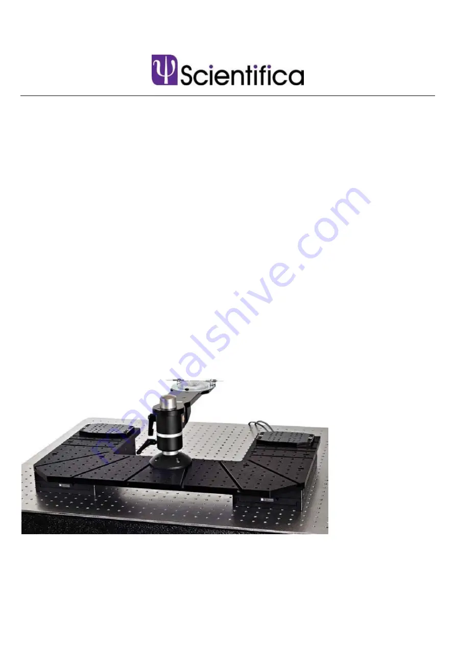
Motorised Moveable
Base Plate (MMBP)
Setup and Operation Manual
Revision 2.0
Manual Part No.: S-MMBP-MANUAL
Page 1: ...Motorised Moveable Base Plate MMBP Setup and Operation Manual Revision 2 0 Manual Part No S MMBP MANUAL...
Page 2: ...Scientifica Ltd 1A Kingfisher Court Brambleside Bellbrook Industrial Estate Uckfield TN22 1QQ United Kingdom Tel 44 0 1825 749 933 Fax 44 0 1825 749 934 info scientifica uk com...
Page 3: ...ing the post onto the MMBP 7 3 2 3 Fitting the locking collar and platform 7 3 2 4 Using the sample plate platform 8 3 2 5 Operating the Post and Platform 9 3 2 6 Adjusting the rotation end stops home...
Page 4: ......
Page 5: ...removal of any screws or components other than those noted in this manual can adversely affect the performance and operation of your stage and may invalidate your warranty 1 2 The Scientifica Motoris...
Page 6: ...e Multiple versions available for compatibility with different upright microscope See section 7 for dimensions These may be supplied with either metric or imperial tapped holes 4 Post and Platform Sam...
Page 7: ...ed below If any of items are missing contact Scientifica Ltd Please retain the packaging for storage or future transportation of the system 2 1 Standard items 1 x MMBP top plate See Figure A for image...
Page 8: ...B type Post and Platform Bath Platform mount components 1 x Stainless Steel Post 350 140 and 90 mm variants available 1 x Screw Down mounting base 1 x Bath platform 1 x Locking Collar with integrated...
Page 9: ...Interfaces one of the following supplied Control Cube Joystick Patch Pad Post and Platform manipulator mounts typically used to mount MicroStar manipulators on the MMBP PP 3400 00 Alternative mounting...
Page 10: ...orm sample plate to the top plate In order to mount your sample on the MMBP a Post and Platform system is supplied For ease of platform positioning you may prefer to fit the post and platform sample p...
Page 11: ...likely to be frequent Be sure to fully lock the carriage in position to ensure sample stability See section 3 2 for instructions on using mounting carriages 3 2 3 Fitting the locking collar and platfo...
Page 12: ...accept chambers from a wide range of manufacturers with a diameter of 108 mm or 110 mm A Platform assembly bolts M5 Do not adjust B M4 tapped holes into side of platform C M3 tapped holes accepts ecc...
Page 13: ...lar lower to the desired height and re tighten 2 Loosen the screw clamp on the platform and lower onto the locking collar locating the screw on the underside of the platform into the end stop groove R...
Page 14: ...he silver upper ring 3 Keeping the platform stationary rotate the silver collar until one end of the groove is in contact with the end stop screw 4 Retighten the grub screw on the silver collar to set...
Page 15: ...Y axis the top plate will therefore need to be positioned carefully to allow full movement and access around the microscope Figure C Orientation of stages 1 Position and attach the post and platform s...
Page 16: ...o hand as it will be required again in later stages of this process FRONT REAR B A Figure Stage mounting holes A Shown driven to the rear to reveal the front mounting holes and B driven to the front t...
Page 17: ...ipping bracket 12 Two rubber membranes are supplied with the MMBP in order to prevent the ingress of solution into the stages Place one of these over each of the stages aligning the holes in the membr...
Page 18: ...prevent damage to the top plate surface The T bar can be mounted to the lower surface of the carriage in any of the five hole positions for additional lateral positioning versatility Figure D Mountin...
Page 19: ...se with the supplied device and controller Changing the connected devices will require reconfiguration of the control rack If you need to alter your setup please contact Scientifica The MMBP is connec...
Page 20: ...16 3 0 Initial Setup 3 3 2 Basic MMBP electrical setup diagram Caution Never connect or disconnect any cables with the 1U Control rack switched on Figure F Basic electrical connections schematic...
Page 21: ...Setup 17 3 3 3 Example system diagram The MMBP can be incorporated into Scientifica s modular electrical system enabling control consoles to be shared between devices Figure G Example system connectio...
Page 22: ...rface supplied Functionality of each user interface type is described as follows 4 2 1 Using a Control cube Figure H Control cube user interface Device selection Located on the side of the cube Select...
Page 23: ...position and the Home Out position The Home Out position must be set first before Home In can be used To set Home Out move the MMBP to the desired position then press H out for 3 seconds to store the...
Page 24: ...nt axis if required Review the Linlab operation manual for more information Device selection switch I II Selects which device to control when two devices and one user interface are connected to a cont...
Page 25: ...or 3 seconds to store the current position Subsequent pressing of Home Out will cause the MMBP to move out to the stored Home Out position until an alternative Home Out position is stored The Home In...
Page 26: ...bles high speed movement When released movement will revert to fine control Memory Pressing the Memory button will store the current position of the MMBP to memory Moving the MMBP and pressing Memory...
Page 27: ...are no user serviceable parts within the MMBP 5 1 Cleaning WARNING Switch off and disconnect the mains supply before cleaning the unit Use a soft cloth dampened with water or a mild detergent to wipe...
Page 28: ...tected with the perfusion running test for longer than 10 minutes Perfusion solution with a temperature different to the room can lead to thermal expansion of the pipette leave some time for the pipet...
Page 29: ...t an external force causing movement of the chamber When using brain slices ensure that the harp use to hold down the slice does so efficiently Check for air currents around the system Open windows or...
Page 30: ...ion 15 to 40 C Storage 0 to 60 C Memory Positions Up to 50 using the Control Device Unlimited via LinLab Bearings Crossed roller 7 1 Top plate schematics All dimensions are in mm All top plates have a...
Page 31: ...7 0 Specifications 27 Figure L Top plate for use with microscopes from Zeiss Olympus and Nikon 1726 Figure M Top plate for use with microscopes from Leica 1850...
Page 32: ...7 0 Specifications 7 2 Sample mounting options All dimensions in mm Figure N Standard bath chamber platform Figure O In vivo long plate mounting platform Figure P In vivo short plate mounting platfor...
Page 33: ...8 2000 XP and Windows 7 1 Insert the supplied CD into your drive PC only 2 Run the LinLab setup exe file 3 Follow the instructions on the screen to complete the installation 8 1 1 Connecting the syste...
Page 34: ...d When running the system on Windows XP or Windows 2000 the operating system should detect a new USB device on power up or connection The following screen will appear Select No not this time Select to...
Page 35: ...tected Note The LinKey driver installation is complete at this point please skip to the section Identifying USB port assignment on the next page Again select No not this time And install from list or...
Page 36: ...ned to the USB port To do this open Control Panel from the Start Menu select System Hardware Device Manger and then expand Ports COM LPT your USB serial Port will be displayed as below in this case as...
Page 37: ...pose of the software is to give you complete control over the set up parameters of your motorised device The following features are in place to optimise the usage of the system 8 2 Running the softwar...
Page 38: ...urrent position will remain as it was prior to switching off 8 2 2 Step Control This function enables the user to drive each axis by a specific amount The user can select any step size between 0 001 a...
Page 39: ...e device to its original position prior to Homing Out less any safety offset which may have been applied using the Set Home In Offset function within the Manipulator menu described below For Manipulat...
Page 40: ...rack and continue If running a single device the following screen allows you to set the correct comms port 8 3 2 Configure System Configuration This allows the user to automatically configure individu...
Page 41: ...you want to do this Once selected the current position is stored as the Home Out position 8 3 4 Manipulator Set Home In Offset This allows you to apply an offset of between 10 mm and 10 mm in micron s...
Page 42: ...r with a virtual axis the step will be applied to the combined axes If an approach angle has not been set the step will only apply to the Z axis 8 3 6 Manipulator Reverse X Y or Z Direction Units This...
Page 43: ...erse the effect of the controller movement i e If you turn the control clockwise and the stage moves to the right click on the Reverse X Joystick and the stage will then move in the opposite direction...
Page 44: ...is menu to set the speed and the distance to be moved 8 3 10 Manipulators PPL Wheel ReMap PPL Wheel re map allows you to swap round which wheels control the different axes To change click Next until t...
Page 45: ...positions In order to store a point within LinLab drive the manipulator or microscope stage to the required location and select AddPoint from the stored points form This will cause the following scree...
Page 46: ...p down menu If you want to cycle through the points select Start Auto Run This will go from one point to the next in a sequential fashion pausing for the time set in the Delay field default is 1000ms...
Page 47: ...eleration for computerised Point to Point moves ie between Home In and Home Out or Memory positions Changes to the acceleration setting also apply to the deceleration value If the user experiences res...
Page 48: ...tton is selected If the user wants to return to the default settings select default and Apply or OK 8 4 Programming linear motion and Heater Cards Scientifica are happy to provide a summary of command...
Page 49: ...o a new Absolute position for the three axis Tabs commas or spaces separate the arguments ABS X Y Z where X Y and Z are positions REL Move Relative This moves to a new Relative position for the three...
Page 50: ...nd compile time PROG Enter Program mode This puts the unit into programming mode ready for Firmware updates JDX Reverse Joystick X Dir This reverses the direction the joystick makes the axis go JDY Re...
Page 51: ...home in Offset for use by the IN command SET Set Home Out position This sets the position the manipulator will go to when OUT is sent to the current position SETSTEP Set Step Size This sets the step w...
Page 52: ...will not apply if the instrument has been damaged by accident misuse or as a result of modification by persons other than Scientifica Ltd personnel Before returning an instrument please obtain a retur...
Page 53: ...Rack mounted controller 15 Figure G Basic electrical connections schematic 16 Figure H Example system connection schematic 17 Figure I Control cube user interface 18 Figure J PatchPad control device 2...
Page 54: ...researchers based on principles of careful design and solid engineering By responding to the unique demands placed on the equipment of electrophysiologists and thinking laterally around these challen...
Page 55: ...Scientifica Ltd 1A Kingfisher Court Brambleside Bellbrook Industrial Estate Uckfield TN22 1QQ United Kingdom Tel 44 0 1825 749 933 Fax 44 0 1825 749 934 info scientifica uk com...