


8-4
Breaker Monitor and Metering Functions
Date Code 20010625
SEL-311L Instruction Manual
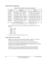
Breaker Monitor Setting Example
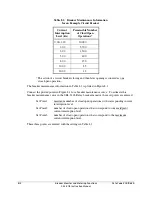
Table 8.2: Breaker Monitor Settings and Settings Ranges
Setting Definition
Range
COSP1
Close/Open set point 1—maximum 0–65000 close/open operations
COSP2
Close/Open set point 2—middle 0–65000 close/open operations
COSP3
Close/Open set point 3—minimum 0–65000 close/open operations
KASP1*
kA Interrupted set point 1—minimum 0.00–999.00 kA in 0.01 kA steps
KASP2
kA Interrupted set point 1—middle 0.00–999.00 kA in 0.01 kA steps
KASP3*
kA Interrupted set point 1—maximum 0.00–999.00 kA in 0.01 kA steps
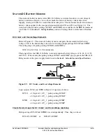
BKMON SEL
OGIC
®
control equation breaker
monitor initiation setting
Relay Word bits referenced in
Tables 9.3 and 9.4
* The ratio of settings KASP3/KASP1 must be: 5
b
KASP3/KASP1
b
100
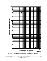
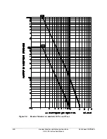
The following settings are made from the breaker maintenance information in Table 8.1 and
Figure 8.1:
COSP1
=
10000
COSP2
=
150
COSP3
=
12
KASP1
=
1.20
KASP2
=
8.00
KASP3
=
20.00
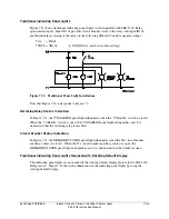
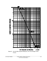
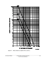
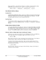
Figure 8.2 shows the resultant breaker maintenance curve.
Breaker Maintenance Curve Details
In Figure 8.2, note that set points KASP1, COSP1 and KASP3, COSP3 are set with breaker
maintenance information from the two extremes in Table 8.1 and Figure 8.1.
In this example, set point KASP2, COSP2 happens to be from an in-between breaker
maintenance point in the breaker maintenance information in Table 8.1 and Figure 8.1, but it
doesn’t have to be. Set point KASP2, COSP2 should be set to provide the best “curve-fit” with
the plotted breaker maintenance points in Figure 8.1.
Each phase (A, B, and C) has its own breaker maintenance curve (like that in Figure 8.2),
because the separate circuit breaker interrupting contacts for phases A, B, and C don’t
necessarily interrupt the same magnitude current (depending on fault type and loading).
Summary of Contents for SEL-311L
Page 6: ......
Page 8: ......
Page 26: ......
Page 54: ......
Page 144: ......
Page 216: ......
Page 252: ......
Page 302: ......
Page 338: ......
Page 480: ......
Page 484: ......
Page 486: ......
Page 502: ......
Page 532: ...12 28 Standard Event Reports and SER Date Code 20010625 SEL 311L Instruction Manual 4 ...
Page 552: ......
Page 554: ......
Page 574: ......
Page 576: ......
Page 596: ......
Page 602: ......
Page 628: ......
Page 656: ......
Page 662: ......
Page 664: ......
Page 688: ......
Page 700: ......
Page 716: ......
Page 722: ......
Page 734: ......