


Date Code 20010625
Inputs, Outputs, Timers, and Other Control Logic
7-17
SEL-311L Instruction Manual
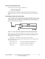
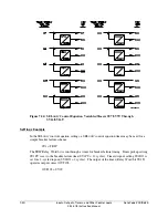
Latch Control Switch States Retained
Power Loss
The states of the latch bits (LT1 through LT16) are retained if power to the relay is lost and then
restored. If a latch bit is asserted (e.g., LT2 = logical 1) when power is lost, it comes back
asserted (LT2 = logical 1) when power is restored. If a latch bit is deasserted (e.g., LT3 =
logical 0) when power is lost, it comes back deasserted (LT3 = logical 0) when power is restored.
This feature makes the latch bit feature behave the same as traditional latching relays. In a
traditional installation, if power is lost to the panel, the latching relay output contact position
remains unchanged.
Note:
Although the relay retains the state of a latched bit when power is cycled, the relay
cannot hold output contact closure when power is removed from the relay (output
contacts go to their deenergized states).
Settings Change or Active Setting Group Change
If individual settings are changed (for the active setting group or one of the other setting groups)
or the active setting group is changed, the states of the latch bits (Relay Word bits LT1 through
LT16) are retained, much like in the preceding “Power Loss” explanation.
If individual settings are changed for a setting group other than the active setting group, there is
no interruption of the latch bits (the relay is not momentarily disabled).
If the individual settings change or active setting group change causes a change in SEL
OGIC
control equation settings SET
n
or RST
n
(
n
= 1 through 16), the retained states of the latch bits
can be changed, subject to the newly enabled settings SET
n
or RST
n
.
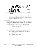
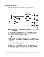
Reset Latch Bits for Active Setting Group Change
If desired, the latch bits can be reset to logical 0 right after a settings group change, using
SEL
OGIC
control equation setting RST
n
(
n
= 1 through 16). Relay Word bits SG1 through SG6
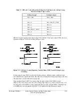
indicate the active setting Group 1 through 6, respectively (see Table 7.3).
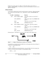
For example, when setting Group 4 becomes the active setting group, latch bit LT2 should be
reset. Make the following SEL
OGIC
control equation settings in setting Group 4:
SV7 = SG4
RST2 = !SV7T + ...
[= NOT(SV7T) + ...]
Summary of Contents for SEL-311L
Page 6: ......
Page 8: ......
Page 26: ......
Page 54: ......
Page 144: ......
Page 216: ......
Page 252: ......
Page 302: ......
Page 338: ......
Page 480: ......
Page 484: ......
Page 486: ......
Page 502: ......
Page 532: ...12 28 Standard Event Reports and SER Date Code 20010625 SEL 311L Instruction Manual 4 ...
Page 552: ......
Page 554: ......
Page 574: ......
Page 576: ......
Page 596: ......
Page 602: ......
Page 628: ......
Page 656: ......
Page 662: ......
Page 664: ......
Page 688: ......
Page 700: ......
Page 716: ......
Page 722: ......
Page 734: ......