


Date Code 20011205
Testing and Troubleshooting
13-19
SEL-311B Instruction Manual
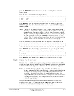
=>>SET L 1 OUT106 <ENTER>
SET L 1 OUT106 <ENTER>
SET L 1 OUT106 <ENTER>
SET L 1 OUT106 <ENTER>
SELogic group 1
OUT106 =0
? 50P1 <ENTER>
50P1 <ENTER>
50P1 <ENTER>
50P1 <ENTER>
OUT107 =0
? END <ENTER>
END <ENTER>
END <ENTER>
END <ENTER>
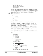
After you type
END <ENTER>
to end the set procedure, the relay displays the
current logic settings. You must continue to type
<ENTER>
to review the full
group of logic settings. At the prompt, type
Y <ENTER>
to accept those settings.
Connect output OUT106 to the sense input of your test set, an ohmmeter, or some
other contact sensing device.
Step 3.
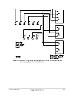
Connect a single current source to a phase current input of the relay. Refer to the
current connections shown in Figure 13.6 as an example.
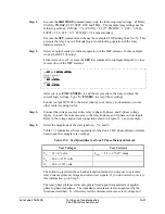
Step 4.
Because the 50P1 overcurrent element operates based upon the magnitude of any
single-phase current, the 50P1 element asserts when any phase current exceeds 11.25
amps.
Step 5.
Turn on the current test source and slowly increase the magnitude of current applied
until the 50P1 element asserts, causing OUT106 to close. This should occur when
current applied is approximately 11.25 amps.
Note:
As you perform this test, other protection elements may assert, causing the relay to
close other output contacts and assert relay targets. This is normal and is not a cause
for concern.
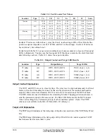
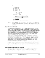
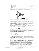
Negative-Sequence Directional Element
The SEL-311B Relay includes phase (F32Q and R32Q) and ground (F32QG and R32QG)
directional elements that operates based upon the calculated magnitude and angle of negative-
sequence impedance applied to the relay. There are two methods of testing these elements. The
first, using a single voltage and current, and the second using three voltages and one current.
Examples of both methods are provided below following an explanation of the equations that
define the element.
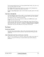
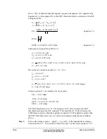
Negative-Sequence Directional Element Based Upon Negative-Sequence Impedance
The SEL-311B Relay calculates the magnitude and angle of negative-sequence voltage and
current applied to the relay. From that information, the relay calculates the magnitude of
negative-sequence impedance that lies collinear to the line positive-sequence impedance. The
equation defining that function is shown below:
(
)
2
2
*
2
2
I
]
I
•
ANG
1
Z
1
•
V
Re[
c
2
Z
°
Ð
=
Equation
13.1
Summary of Contents for SEL-311B
Page 6: ......
Page 8: ......
Page 10: ......
Page 24: ......
Page 26: ......
Page 122: ......
Page 124: ......
Page 138: ......
Page 168: ......
Page 172: ......
Page 254: ......
Page 282: ......
Page 306: ......
Page 348: ......
Page 364: ......
Page 366: ......
Page 448: ......
Page 460: ......
Page 466: ......
Page 476: ......
Page 482: ......
Page 494: ......
Page 500: ......
Page 522: ......
Page 526: ......
Page 528: ......
Page 534: ......
Page 536: ......
Page 550: ......
Page 570: ......
Page 586: ......
Page 600: ......


