


6-22
Close and Reclose Logic
Date Code 20011205
SEL-311B Instruction Manual
Drive-to-Lockout and Drive-to-Last Shot Settings (79DTL and 79DLS, Respectively)
When 79DTL = logical 1, the reclosing relay goes to the Lockout State (Relay Word bit
79LO = logical 1), and the front
-
panel LO (Lockout) LED illuminates.
79DTL has a 60-cycle dropout time. This keeps the drive-to-lockout condition up 60 more
cycles after 79DTL has reverted back to 79DTL = logical 0. This is useful for situations where
both of the following are true:
·
Any of the trip and drive-to-lockout conditions are “pulsed” conditions (e.g., the
OPE
command Relay Word bit, OC, asserts for only 1/4 cycle—refer to the following
Settings Example
).
·
Reclose initiation is by the breaker contact opening (e.g., 79RI = !52A—refer to
Additional Settings Example
in the preceding setting 79RI [reclose initiation]
discussion).
Then the drive-to-lockout condition overlaps reclose initiation and the SEL-311B stays in
lockout after the breaker trips open.
When 79DLS = logical 1, the reclosing relay goes to the last shot, if the shot counter is not at a
shot value greater than or equal to the calculated last shot (see
Reclosing Relay Shot Counter
earlier in this subsection).
Settings Example
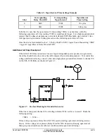
The drive-to-lockout example setting is:
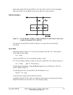
79DTL = !IN102 + LB3 + OC
Optoisolated input IN102 is set to operate as a reclose enable switch (see
Optoisolated Inputs
in
Section 7: Inputs, Outputs, Timers, and Other Control Logic
). When Relay Word bit
IN102 = logical 1 (reclosing enabled), the relay is not driven to the Lockout State (assuming
local bit LB3 = logical 0, too):
!IN102 = !(logical 1) = NOT(logical 1) = logical 0
79DTL = !IN102 + LB3 + OC = (logical 0) + LB3 = LB3 + OC
When Relay Word bit IN102 = logical 0 (reclosing disabled), the relay is driven to the Lockout
State:
!IN102 = !(logical 0) = NOT(logical 0) = logical 1
79DTL = !IN102 + LB3 + OC = (logical 1) + LB3 + OC = logical 1
Local bit LB3 is set to operate as a manual trip switch (see
Local Control Switches
in
Section 7:
Inputs, Outputs, Timers, and Other Control Logic
and
Trip Logic
in
Section 5: Trip and
Target Logic
). When Relay Word bit LB3 = logical 0 (no manual trip), the relay is not driven to
the Lockout State (assuming optoisolated input IN102 = logical 1, too):
79DTL = !IN102 + LB3 + OC = NOT(IN102) + (logical 0) + OC = NOT(IN102) + OC
When Relay Word bit LB3 = logical 1 (manual trip), the relay is driven to the Lockout State:
79DTL = !IN102 + LB3 + OC = NOT(IN102) + (logical 1) + OC = logical 1
Summary of Contents for SEL-311B
Page 6: ......
Page 8: ......
Page 10: ......
Page 24: ......
Page 26: ......
Page 122: ......
Page 124: ......
Page 138: ......
Page 168: ......
Page 172: ......
Page 254: ......
Page 282: ......
Page 306: ......
Page 348: ......
Page 364: ......
Page 366: ......
Page 448: ......
Page 460: ......
Page 466: ......
Page 476: ......
Page 482: ......
Page 494: ......
Page 500: ......
Page 522: ......
Page 526: ......
Page 528: ......
Page 534: ......
Page 536: ......
Page 550: ......
Page 570: ......
Page 586: ......
Page 600: ......


