9-8
Setting the Relay
Date Code 20011205
SEL----311A Instruction Manual
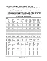
Row
Relay Word Bits
35
* * * * * * * *
36
*
*
*
*
MPP1 MABC1
MPP2 MABC2
37
* * * * * * * *
38
* * * * * * * *
39
* * * * * * * *
40
* * * * * * * *
41
* * * * * * * *
42
* * * * * * * *
43
* * * * * * * *
44
* * * * * * * *
45
* * * * * * * *
46
* * * * * * * *
47
RMB8A RMB7A RMB6A RMB5A RMB4A RMB3A RMB2A RMB1A
48
TMB8A TMB7A TMB6A TMB5A TMB4A TMB3A TMB2A TMB1A
49
RMB8B RMB7B RMB6B RMB5B RMB4B RMB3B RMB2B RMB1B
50
TMB8B TMB7B TMB6B TMB5B TMB4B TMB3B TMB2B TMB1B
51
LBOKB CBADB RBADB ROKB
LBOKA CBADA RBADA ROKA
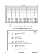
1. See Figure 7.1 for more information on the operation of optoisolated inputs IN101 through
IN106.
2. All output contacts can be “a” or “b” type contacts. See Figure 2.7 and Figure 7.26 for more
information on the operation of output contacts OUT101 through ALARM.
Table 9.4: Relay Word Bit Definitions for the SEL-311A
Row
Bit
Definition
Primary
Application
0 EN
Relay
enabled (see Table 5.1)
Target
TRP
Relay
trip
TIME
Time delayed trip
TARDT
Direct
trip
target
SOTF
Switch-onto-fault
trip
TARLOP
Loss-of-potential
target
TAR51P
Phase time-overcurrent target
TAR51G
Residual ground time-overcurrent target
1
A
Phase A is involved in the fault (see Table 5.1)
B
Phase B is involved in the fault
C
Phase C is involved in the fault
G
Residual ground element tripped for fault or residual
ground current above pickup of residual ground
element at time of trip
Summary of Contents for SEL-311A
Page 6: ......
Page 8: ......
Page 10: ......
Page 24: ......
Page 40: ......
Page 66: ......
Page 96: ......
Page 98: ......
Page 112: ......
Page 114: ......
Page 122: ......
Page 170: ......
Page 202: ......
Page 204: ......
Page 246: ......
Page 248: ......
Page 286: ......
Page 290: ......
Page 304: ......
Page 306: ......
Page 334: ......
Page 384: ......
Page 386: ......
Page 394: ......
Page 398: ......
Page 402: ......
Page 404: ......
Page 410: ......
Page 412: ......
Page 426: ......
Page 444: ......
Page 460: ......
Page 474: ......

