7-38
Inputs, Outputs, Timers, and Other Control Logic
Date Code 20011205
SEL-311A Instruction Manual
This results in the display of corresponding text setting DP2_1 on the front-panel display:
BREAKER CLOSED
Circuit Breaker Open
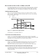
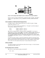
In Figure 7.28, optoisolated input IN101 is deenergized when the 52a circuit breaker auxiliary
contact is open, resulting in:
DP2 = IN101 = logical 0
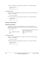
This results in the display of corresponding text setting DP2_0 on the front-panel display:
BREAKER OPEN
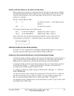
Additional Settings Examples
Display Only One Message
To display just one screen, but not its complement, set only one of the text settings. For
example, to display just the “breaker closed” condition, but not the “breaker open” condition,
make the following settings:
DP2 = IN101
(52a circuit breaker auxiliary contact connected to
input IN101—see Figure 7.28)
DP2_1 = BREAKER CLOSED
(displays when DP2 = logical 1)
DP2_0 =
(blank)
Circuit Breaker Closed
In Figure 7.28, optoisolated input IN101 is energized when the 52a circuit breaker auxiliary
contact is closed, resulting in:
DP2 = IN101 = logical 1
This results in the display of corresponding text setting DP2_1 on the front-panel display:
BREAKER CLOSED
Summary of Contents for SEL-311A
Page 6: ......
Page 8: ......
Page 10: ......
Page 24: ......
Page 40: ......
Page 66: ......
Page 96: ......
Page 98: ......
Page 112: ......
Page 114: ......
Page 122: ......
Page 170: ......
Page 202: ......
Page 204: ......
Page 246: ......
Page 248: ......
Page 286: ......
Page 290: ......
Page 304: ......
Page 306: ......
Page 334: ......
Page 384: ......
Page 386: ......
Page 394: ......
Page 398: ......
Page 402: ......
Page 404: ......
Page 410: ......
Page 412: ......
Page 426: ......
Page 444: ......
Page 460: ......
Page 474: ......


