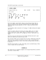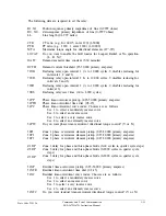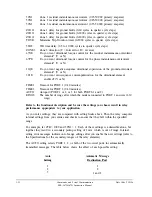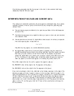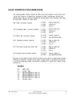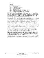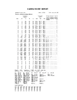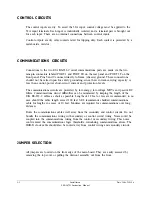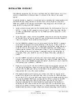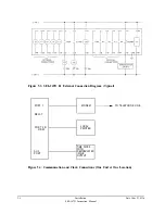
The following paragraphs describe the response of the relay to this simulated fault using
information from the full event report.
INTERPRETATION OF VOLTAGE AND CURRENT DATA
The voltage and current data provided in the event report are determined using the secondary
quantities presented to the rear panel of the SEL-267D relay through the processing steps
outlined below.
The input analog signals are filtered by two-pole low-pass filters with cutoff frequencies
of about 85 Hz.
The filtered analog signals are sampled four times per power system cycle and converted
into numerical values.
The sampled data are processed by digital filters which remove dc and ramp components.
The unit sample response of these filters is:
1, -1, -1, 1
This filter has the property of a double differentiator-smoother.
The digital filter output data are scaled into primary quantities using the current and
potential transformer ratios entered in the setting procedure. Since the samples are taken
four times per power system cycle and the four most recent samples are processed
through the digital filter every quarter cycle, successive outputs of the filter arrive every
90°. So, with respect to the present value of the filter output, the previous value was
taken one-quarter cycle earlier and appears to be leading the present value by 90°.
These filter output values can be used to represent the signals as phasors:
The PRESENT value of the output is the X-component of the phasor.
The PREVIOUS value of the output is the Y-component of the phasor.
It may seem confusing to refer to the older data as the leading component of the phasor. The
following example may help. Consider a sinewave with zero phase shift with respect to t=0
and a peak amplitude of 1. Now consider two samples, one taken at t=0, and the other taken
90° later. They have values 0 and 1, respectively. By the above rules, the phasor compo-
nents are (X,Y) = (1,0). Now consider a cosine function. Its samples, taken at the same
time instants, are 1 and 0, while its phasor representation is (0,l). The phasor (0,l) leads the
phasor (1,0) by 90°
,
and this agrees with the 90° lead of the cosine function with respect to
the sine function.
Date Code 920326
Event Reporting
SEL-267D/167D Instruction Manual
4-3
Summary of Contents for SEL-167D
Page 3: ......
Page 6: ......
Page 8: ......
Page 9: ......
Page 10: ......
Page 11: ......
Page 51: ...LOGIC DIAGRAMS Date Code 920326 Specifications SEL 267D 167D Instruction Manual 2 31 ...
Page 52: ...Date Code 920326 Specifications 2 32 SEL 267D 167D Instruction Manual ...
Page 53: ...Date Code 920326 Specifications SEL 267D 167D Instruction Manual 2 33 ...
Page 54: ...Date Code 920326 Specifications SEL 267D 167D Instruction Manual 2 34 ...
Page 88: ...SAMPLE EVENT REPORT ...
Page 114: ......
Page 115: ......

