


The A2 output relay on terminals monitors the demand current threshold. Since the demand
current exceeds the demand current threshold, the A2 output relay operates for all of the
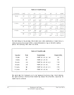
faults shown in the first table.
The A3 output relay on terminals monitors the residual time-overcurrent trip (51NT). Since
the fault condition persists longer than the 51N time delay, the output relay A3 operates for
any of the ground faults shown in the first table as determined by the settings.
The output relay A4 at terminals is set to monitor the phase time-overcurrent trip (51PT).
The polyphase time-overcurrent relay element operates on the largest phase current magni-
tude. Therefore, the A4 output asserts for both phase and ground faults as shown in the
table.
The LOGIC command section provides a detailed description of the programming of the
output relays A1-A4 and six other logic masks (MRC, MRI, etc.).
The Zone 1 ground fault target (G1) illuminated for the ground fault at 9 miles because the
Zone 1 ground overcurrent relay element caused the trip (ZlDG set to zero or instantaneous
trip for the example 69 kV line). The displayed targets generally disclose the relay element
that caused the trip to occur for the fault. The fault targets are automatically cleared by the
next fault, before the new fault targets are presented.
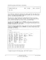
Each fault generates a short event report. Type
EVENT 1
and press
<ENTER>
to display
a full event report for the last fault. The report provides an eleven cycle record of the
currents, voltages, relay element states, and states of all contact inputs and outputs. The
twelve newest reports are saved.
This checkout procedure demonstrates only a few of the features of the relay. Study the
FUNCTIONAL DESCRIPTION, COMMAND, and EVENT REPORT sections of this
manual to obtain a complete understanding of the capabilities of the relay.
FUNCTIONAL TESTS
Setting Test
To make sure the relay accepts settings, perform the following steps:
1.
Gain Level 2 Access (see ACCESS and 2ACCESS commands).
2.
Type
SET
and press
<ENTER>.
3.
Change one setting. For example, change the maximum torque angle (MTA) from 49°
to 60°.
Date Code 920326
Maintenance and Testing
SEL-267D/167D Instruction Manual
6-5
Summary of Contents for SEL-167D
Page 3: ......
Page 6: ......
Page 8: ......
Page 9: ......
Page 10: ......
Page 11: ......
Page 51: ...LOGIC DIAGRAMS Date Code 920326 Specifications SEL 267D 167D Instruction Manual 2 31 ...
Page 52: ...Date Code 920326 Specifications 2 32 SEL 267D 167D Instruction Manual ...
Page 53: ...Date Code 920326 Specifications SEL 267D 167D Instruction Manual 2 33 ...
Page 54: ...Date Code 920326 Specifications SEL 267D 167D Instruction Manual 2 34 ...
Page 88: ...SAMPLE EVENT REPORT ...
Page 114: ......
Page 115: ......


