


Assembly
occurs either via two pneumatic plug connections G1/8" 6/4 or
two sealing nipples for locking couplings type NW 7.4 (accessory).
The clamping station can be retrofitted at the connection points
using a separately available connecting strip (accessory).
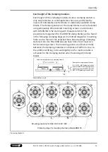
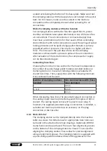
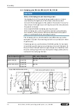
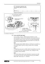
Reduced material
thickness in marked
areas
Bore holes permitted in
shaded areas
NSL3 200
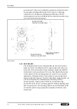
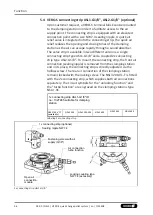
4.3.3 NSL3 200-V1-T
The clamping station can be clamped directly onto the machine
table via screws. Permitted areas for appropriate bore holes can
be found in the attached bore hole drawings. Optionally, BRR 50
clamp banks can be purchased. There are four alignment grooves
on the bottom of the clamping station to mount T-nuts used for
aligning the clamping station. These allow for precise alignment
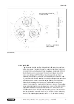
along an alignment groove. The NSL3 200-V1-T is equipped with
two interconnected G 1/8" air connections for simultaneously
unlocking both clamping points. Two additional interconnected G
1/8" air connections to the supply of the turbo function at both
clamping points. The air supply can be connected to either the
front or the back of the clamping station. The opposing connection
points are closed with locking screws. Supply occurs either via two
pneumatic plug connections G1/8" 6/4 or two sealing nipples for
locking couplings type NW 7.4 (accessory). The clamping station is
equipped with quick-change pallet modules with two fitting
23
03.00 | NSL3 | VERO-S quick-change pallet system | en | 1155408


