Assembly
32
01.00|KSP3-IM, KSP3-LH-IM |en
Assembly and adjustment of the proximity switches
For TANDEM KSP3-IM/KSP3-LH-IM, two inductive proximity
switches have been fitted. The proximity switches can be moved
on the retaining plate (item 12) so that the switching point can be
individually adjusted. The proximity switches are used for
monitoring the jaw stroke end position for O.D. and I.D. clamping
as well as for monitoring the clamping position.
Adjust the switching point of proximity switch "
S1
" (installed on
the left) so that the required switching signal is present when the
stroke end position is "open" or "closed."
Proximity switch "
S2
" is used for monitoring the clamping position
between the two jaw end positions. Adjust the switching point so
that a switching signal is present in the area of the clamping
position. Exceeded workpiece tolerances can be monitored via the
signal output of switch "
S2
".
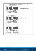
The function and circuit diagram for adjusting the proximity
switches is shown in illustrations 6, 7 and 8. The proximity
switches are equipped with an LED signal display on the sensor
head.
Insert the counter-supports (item 13) into the retaining plate (item
12). Screw both proximity switches (item 36) together with
hexagon nuts and washers (item 72) through the retaining plate
into the counter-support with the sensor head facing forward so
that the switches are flush or project slightly. Tighten the retaining
plate (item 12) together with the cover (item 14) using the screw
(item 71) in the recess of the clamping force block. To fine-tune
the switching distance, manually screw in each proximity switch
until it stops at the base jaw and then unscrew it by approximately
1.5 turns. The connection cable must not be excessively twisted
nor damaged in any way. When making the adjustment, make sure
that the signal LED on the sensor is easily visible. Then fasten the
proximity switch to the retaining plate (item 12) using the counter
nut.
5.4.4


