background image


Basic safety notes  


01.00|KSH3, KSH3-LH, KSH3-F |en 


Basic safety notes  


Intended use 

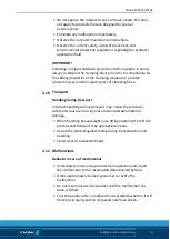
  •  This product is intended for clamping and holding workpieces 

on machine tools and other suitable technical devices. 

  •  It is designed to be set up on a machine table or machine 

pallets. 

  •  The product may only be used within the scope of its technical 

data, 

(

 3, Page 16)

. 

  •  The product is intended for industrial and industry-oriented 

use. 

  •  Appropriate use of the product includes compliance with all 

instructions in this manual. 


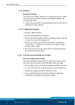
Not intended use 

The product is not being used as intended if, for example: 
  •  It is used as lifting equipment, as a press, as a punching tool, as 

a lathe chuck, as a drill or as a cutting tool. 

  •  It is used in working environments that are not permissible. 
  •  Workpieces are not properly clamped. 
  •  Safety regulations are disregarded and persons are working at 

this product (for example, to machine clamped workpieces) 

without additional protective equipment. 

  •  The technical data specified by the manufacturer are exceeded 

during usage. 

  •  It is used with machines/systems or workpieces that are not 

designed to be used with it. 


2.1 

2.2 

Summary of Contents for TANDEM KSH3

Page 1: ...Translation of the Original Operating Manual TANDEM Clamping Force Block KSH3 KSH3 LH KSH3 F Assembly and Operating Manual Superior Clamping and Gripping ...

Page 2: ...wned company the leading technology supplier of robots and production machines Our team is always available to answer any questions on this product and other solutions Ask us questions and challenge us We will find a solution Best regards Your SCHUNK team H D SCHUNK GmbH Co Spanntechnik KG Lothringer Str 23 D 88512 Mengen Tel 49 7572 7614 0 Fax 49 7572 7614 1099 info de schunk com schunk com Custo...

Page 3: ...9 Notes on safe operation 10 2 10 Transport 11 2 11 Malfunctions 11 2 12 Disposal 12 2 13 Fundamental dangers 12 2 13 1 Protection during handling and assembly 12 2 13 2 Protection during commissioning and operation 13 2 13 3 Protection against dangerous movements 13 2 13 4 Notes on particular risks 14 3 Technical data 16 4 Tightening torques for screws 19 5 Assembly and connection 20 5 1 Assembly...

Page 4: ...htness of the hydraulic system 35 7 4 4 Assembly devices piston seals 36 8 Sealing kits accessory kits and parts lists 38 8 1 Sealing kit lists 38 8 1 1 Piston chamber sealing kit 38 8 1 2 Monitoring sealing kit connection 39 8 2 Accessory kits 39 8 3 Parts lists 40 9 Assembly drawings 45 9 1 KSH3 KSH3 LH 45 9 2 KSH3 F 46 10 Translation of the original declaration of incorporation 47 11 Appendix o...

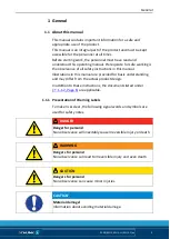
Page 5: ...ustrations in this manual are provided for basic understanding and may differ from the actual product design In addition to these instructions the documents listed under 1 1 2 Page 6 are applicable Presentation of Warning Labels To make risks clear the following signal words and symbols are used for safety notes DANGER Danger for persons Non observance will inevitably cause irreversible injury or ...

Page 6: ...very date from factory or 500 000 cycles if it is used as intended under the following conditions Observe the applicable documents 1 1 2 Page 6 Observe the ambient conditions and operating conditions 2 6 Page 9 Observance of the specified care and maintenance instructions 7 Page 28 Parts touching the workpiece and wear parts are not included in the warranty A cycle consists of a complete clamping ...

Page 7: ...iance with all instructions in this manual Not intended use The product is not being used as intended if for example It is used as lifting equipment as a press as a punching tool as a lathe chuck as a drill or as a cutting tool It is used in working environments that are not permissible Workpieces are not properly clamped Safety regulations are disregarded and persons are working at this product f...

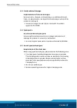
Page 8: ...rts can endanger personnel and damage the product or cause it to malfunction Use only original spare parts or spares authorized by SCHUNK Use of special chuck jaws Requirements of the chuck jaws When using special chuck jaws please observe the following rules The chuck jaws should be designed to be as low as possible The clamping point must be as close as possible to the housing clamping points at...

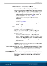
Page 9: ...rsonnel working with the product is not sufficiently qualified the result may be serious injuries and significant property damage All work may only be performed by qualified personnel Before working with the product the personnel must have read and understood the complete assembly and operating manual Observe the national safety regulations and rules and general safety instructions The following p...

Page 10: ... personal protective equipment Observe the valid safety and accident prevention regulations Wear protective gloves to guard against sharp edges and corners or rough surfaces Wear heat resistant protective gloves when handling hot surfaces Wear protective gloves and safety goggles when handling hazardous substances Wear close fitting protective clothing and also wear long hair in a hairnet when dea...

Page 11: ...oss of clamping force Transport Handling during transport Incorrect handling during transport may impair the product s safety and cause serious injuries and considerable material damage When handling heavy weights use lifting equipment to lift the product and transport it by appropriate means Secure the product against falling during transportation and handling Stand clear of suspended loads Malfu...

Page 12: ...isconnect power sources before installation modification maintenance or calibration Ensure that no residual energy remains in the system Do not reach into the open mechanism or movement area of the product during operation Protection during handling and assembly Incorrect handling and assembly Incorrect handling and assembly may impair the product s safety and cause serious injuries and considerab...

Page 13: ...t reactivation Never rely merely on the response of the monitoring function dynamic pressure monitoring with pressure sensors to avert danger Assume that the drive movement is faulty as long is the installed monitors are not effective since the effect depends on the control and the current operating state of the drive Perform maintenance modification and attachment work outside of the danger zone ...

Page 14: ... user program in case of pressure loss WARNING Risk of injury from falling parts during transport assembly and disassembly of the product and its accessories Use suitable load handling equipment for transport Do not remain in the danger zone Wear protective equipment protective shoes WARNING Danger of crushing due to the chuck jaws approaching the workpiece during the clamping procedure when loadi...

Page 15: ...product using manual force Use load handling equipment for lifting and transporting CAUTION Allergic reactions or irritation due to skin or eye contact with lubricants on the product In case of foreseeable contact with lubricants on the product e g when lubricating or cleaning wear protective equipment protective gloves protective goggles ...

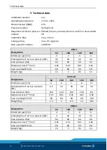
Page 16: ...t max pressure kN 4 5 18 30 45 max pressure bar 60 60 60 60 Repeat accuracy mm 0 01 0 01 0 01 0 01 max jaw height mm 60 60 60 60 Weight kg 1 5 5 9 5 14 Designation KSH3 LH 64 100 140 160 250 Stroke per jaw mm 4 6 7 8 15 Clamping force at max pressure kN 4 5 16 30 40 50 max pressure bar 120 120 120 120 60 Repeat accuracy mm 0 01 0 01 0 01 0 01 0 02 max jaw height mm 60 60 60 60 150 Weight kg 1 5 5 ...

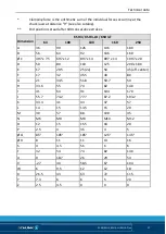
Page 17: ... 4H7 x 7 5 6H7 x 12 8H7 x 14 8H7 x 14 10H7 x 20 D 50 80 110 125 200 x 180 E 17 29 5 25 2x 50 45 off center F 17 32 45 5 40 80 G 21 34 5 51 8 59 7 50 H 33 6 55 74 82 140 I 41 64 91 104 170 J 55 7 74 2 77 7 87 2 103 2 K 33 3 41 43 47 57 L 14 15 13 5 15 20 M 30 57 88 100 45 N M6 M8 M8 M10 M12 O 12 15 15 5 18 20 P 2 5 4 3 5 4 5 Ø Q 8f7 10f7 10f7 12f7 14f7 Ø R 8 11 11 13 16 S 4 4 5 5 5 6 6 T 32 54 74 8...

Page 18: ...data 18 01 00 KSH3 KSH3 LH KSH3 F en 1 Optional Z variant 0 01 mm to clamping center 2 Clamping sleeve 0 04 mm to clamping center 3 Clamping sleeve fitting screw 0 02 mm to clamping center 4 Only with variant PM ...

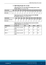
Page 19: ... 120 160 200 290 400 500 Tightening torques for mounting top jaws on the TANDEM clamping force block screw quality 12 9 Screw size M4 M5 M6 M8 M10 M12 M14 M16 M20 M24 Tightening torques MA Nm 5 9 15 32 62 108 170 262 510 880 Tightening torques for mounting the chuck piston onto the cylinder piston screw quality 12 9 Designation Screw size M5 M8 M10 M12 KSH3 Tightening torque MA Nm 9 32 62 108 KSH3...

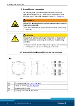
Page 20: ...ne table during assembly Do not reach between the product and machine table during assembly CAUTION Danger of abrasions due to rough components of the product and its accessories which may slip out of your hands during assembly Wear protective equipment protective gloves when working on the product and when handling its accessories Assembly of the Clamping Block on the machine table 34 Cylindrical...

Page 21: ...s in the housing item 1 that along with the fitting screws item 82 are used to center the clamping force block on the machine table with repeat accuracy Do not realign the clamping force block after removing it from the machine table e g after replacing the seals When using fitting screws item 82 these are used instead of the clamping sleeves item 85 and two of the four screws item 84 Mounting wit...

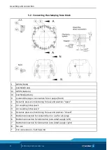
Page 22: ...e front 1 Dynamic pressure monitoring for jaw end position open 2 Air coupling in top jaw 1 3 Air coupling in top jaw 2 4 Dynamic pressure monitoring for jaw end position closed 5 Bottom connection for coolant drain or use for air purge 6 Bottom connection for lubrication one sided supply left 7 Bottom connection for lubrication one sided supply right 8 No use For connection 1 7 with size 64 5 2 ...

Page 23: ... With the delivery of the clamping force block all four hydraulic connections are sealed On the base side with set screws item 60 and on the front with locking screws item 23 When using the air purge via connection 5 the sound absorber V must be removed and replaced by a set screw item 93 8 2 Page 39 The clamping force block has two more base connections 6 7 for direct lubrication through the mach...

Page 24: ...ction 3 1 Work surface Dimension Size 64 100 140 160 250 KTR KTR H KTR KTR H KTR KTR H KTR KTR H KTR KTR H B1 mm 4 5 4 5 14 14 18 5 18 5 28 28 36 36 B2 mm 18 18 35 35 46 5 41 5 56 51 80 75 T1 mm 11 30 18 43 27 62 30 70 35 85 T2 mm 4 23 9 34 15 50 19 59 21 71 Ø C mm 2 2 2 2 2 D mm 7 3 6 6 5 20 E mm 3 5 5 5 1 1 1 F mm 2 0 1 2 0 1 2 0 1 2 0 1 2 5 0 1 Non tolerated dimensions according to DIN ISO 2768...

Page 25: ... D E and F must be observed Dynamic pressure monitoring of the workpiece flat work surface For this purpose the customer must provide the top jaw with a Ø2 mm monitoring hole on the workpiece flat work surface This ensures that the escaping air pressure can be released up to where contact is made with the mounted workpiece and that a differential pressure measurement can be carried out via a diffe...

Page 26: ... KSH3 F en Hydraulic circuit diagram Jaw stroke open Jaw stroke close 1 Dynamic pressure monitoring for jaw end position open 2 bar 2 Air coupling in top jaw 1 3 Air coupling in top jaw 2 4 Dynamic pressure monitoring jaw stroke closed 2 bar 5 2 4 ...

Page 27: ...ble cause Solution s Clamping force block not sealed tightly Check connection and seal screws reseal or replace Seals damaged Disassemble clamping force block 7 4 2 Page 34 and replace all the seals see sealing kit lists 8 1 Page 38 Inadequate lubrication Lubricate the lubrication nipples with LINOMAX 200 7 Page 28 Clamping force block movement jerky Possible cause Solution s Steel guide rollers o...

Page 28: ...n intervals The following maintenance work should be carried out after the specified cycle numbers or at the latest after the monthly data Maintenance work Interval cycles month Lubricate 10 000 1 Basic cleaning 6 Leak test 5 000 1 Greasing areas lubricants Greasing areas Lubricant Sliding surfaces body base jaw LINOMAX 200 Sliding surfaces base jaws chuck piston LINOMAX 200 Lubrication nipples LI...

Page 29: ...nts on the product e g when lubricating or cleaning wear protective equipment protective gloves protective goggles To maintain reliable function and high quality of the product it has to be regularly lubricated This can be done with a hand lever press for greases or by means of central lubrication Manual lubrication Press grease either into the grease nipples at the side or front of the respective...

Page 30: ... After greasing run through the complete stroke several times Grease to be used and lubrication intervals 7 3 Page 28 Size Grease quantity per connection cm 64 2 100 4 140 4 160 4 250 4 Basic cleaning For basic cleaning the product must be disassembled cleaned and reassembled With the PM variant the pneumatic jaw end position control must also be set Before disassembling the product switch off the...

Page 31: ...ws 64 and take off the cover strip 8 Remove screws 66 and take off the guide strip 6 Variant PM also includes a compression spring 27 O ring 43 sphere 24 and O ring 42 Remove screws 65 and pull out cover 5 together with O ring 45 and O rings 42 out of the housing To do this screw two screws into the threaded holes as an extraction tool for size 64 M3 x L 25 for size 100 M3 x L 25 for size 140 M4 x...

Page 32: ...ousing Additionally for the KSH3 F variant Remove screw 68 Pull out the positioning bolt 10 via its extraction thread with a screw as far as the stop Pull the base jaw 9 out of the housing Variant PM also includes the O ring 44 Pull the base jaws 2 out of the housing Variant PM also includes O ring 44 monitoring piece 7 and compression springs 26 Caution The monitoring piece is under spring pre lo...

Page 33: ...of disassembly In doing so observe the following Pay attention to the mounting position of the base jaws item 2 and the chuck piston item 3 Observe the tightening torques for the screws 4 Page 19 After completion of the assembly carry out a leak test and a function test 7 4 3 Page 35 Variant PM Pay attention to the correct alignment of the monitoring pieces Readjust the pneumatic jaw end position ...

Page 34: ... differential pressure sensor emits a switching signal Hand tighten set screw 61 in bore hole o Screw set screw 63 in both bore holes and hand tighten Jaw 2 monitoring closed jaw position Move base jaws to CLOSED position Screw the set screw 61 into the bore hole oo up to the stop and then unscrew it again by a few turns Slowly screw the set screw 61 into the bore hole o until the differential pre...

Page 35: ...nd CLOSED connections 3 Link the supply line and hydraulic coupling to the hydraulic screw fittings The leakage and tightness test is to be performed in the following order 1 Actuate the clamping force block with reduced hydraulic pressure Check the clamping force block for free movement by opening and closing the jaws several times 2 Check the clamping force block with the maximum permissible hyd...

Page 36: ...ll the O ring of the seal item 40 over the cylinder piston item 4 and into the groove Do not stretch or tear the O ring in the process Stretch the sealing ring with an expansion sleeve over the cone sleeve and slide over the cylinder piston and the O ring that was previously inserted into the groove 2 Calibration After sliding it over the Turcon ring snaps into the groove However assembly is still...

Page 37: ... expansion sleeve Material POM NYLON or similar KSH3 Piston Ø D d1 d2 d3 L I1 t1 0 3 xyz 64 21 20 37 16 37 12 37 5 76 71 63 3x120 100 35 34 64 30 64 26 64 17 81 76 68 3x120 140 50 48 94 44 94 40 94 25 86 81 73 4x90 160 58 55 22 51 22 47 22 28 91 86 78 4x90 250 120 115 54 11 54 107 54 58 106 101 93 6x60 C calibration sleeve Material steel KSH3 Piston Ø D d1 L I1 I2 1 64 21 29 05 21 05 30 1 10 100 3...

Page 38: ...the piston chamber piston chamber sealing kit and one for the pneumatic monitoring monitoring sealing kit The sealing elements for the bottom connections are included in both sealing kits Piston chamber sealing kit The sealing kit for the piston chamber contains all seals for the parts installed inside e g cylinder pistons as well as the O rings of the bottom connections Sealing kit ID number Size...

Page 39: ...ber Size 64 1470480 Size 100 1470390 Size 100 LH 1470468 Size 140 1470482 Size 160 1470397 Size 250 1470398 For included items see column y in the Parts List chapter below Wearing parts replacement when maintenance is performed is recommended The sealing kit can only be ordered as a compete kit Accessory kits Accessory kit ID number Size 64 1446553 Size 100 1446556 Size 140 1446557 Size 160 144655...

Page 40: ...w 2 3 Chuck piston 1 4 Cylinder piston 1 5 Cover 1 6 Guide strip 2 7 Monitoring piece 2 8 Covering strip 1 21 Funnel nipple 4 21 Conical lubrication nipple 4 22 Sound absorber 1 23 Locking screw 2 24 Steel ball 2 26 Compression spring 4 27 Compression spring 2 34 Cylindrical pin 2 40 Turcon Glyd Ring 1 41 Turcon Glyd Ring 1 42 O ring DIN ISO 3601 11 12 2 43 O ring DIN ISO 3601 2 44 O ring DIN ISO ...

Page 41: ...4 61 Set screw 4 62 Set screw 7 8 6 63 Set screw 4 64 Countersunk screw ISO 14581 2 65 Countersunk screw 9 Cylindrical screw 7 15 13 66 Cylindrical screw 2 69 Screw 1 70 Set screw 2 3 4 81 Plug 4 82 Fitting screw 2 83 O ring DIN ISO 3601 4 84 Screw 4 85 Clamping sleeve 2 86 Screw 8 87 O ring DIN ISO 3601 2 10 88 O ring DIN ISO 3601 7 ...

Page 42: ...jaw 1 3 Chuck piston 1 4 Cylinder piston 1 5 Cover 1 6 Guide strip 2 1 7 Monitoring piece 1 8 Covering strip 1 9 Base jaw 1 10 Bolt 1 11 Guide strip 1 21 Cupped type lubrication nipples 4 21 Conical lubrication nipple 4 22 Sound absorber 1 23 Locking screw 2 24 Steel ball 2 26 Compression spring 2 27 Compression spring 2 34 Cylindrical pin 2 40 Turcon Glyd Ring 1 41 Turcon Glyd Ring 1 42 O ring DI...

Page 43: ...47 Sealing ring 1 60 Set screw 2 4 61 Set screw 2 62 Set screw 7 8 6 63 Set screw 2 64 Countersunk screw 2 65 Countersunk screw 9 Cylindrical screw 7 15 13 1 66 Cylindrical screw 1 67 Cylindrical screw 1 68 Cylindrical screw 1 69 Screw 2 70 Set screw 3 4 4 81 Plug 2 82 Fitting screw 4 83 O ring DIN ISO 3601 4 84 Screw 2 85 Clamping sleeve 8 86 Screw 2 ...

Page 44: ...et screw 2 100 T handle Parts list key a for all sizes y wearing part b for size 64 included in the piston chamber sealing kit c for size 100 included in the monitoring sealing kit d for size 140 z included in accessory kit e for size 160 f for size 250 Individual components are specially tuned to one another and cannot be replaced by the customer ...

Page 45: ...ly drawings 01 00 KSH3 KSH3 LH KSH3 F en 45 Assembly drawings KSH3 KSH3 LH A with variant PM B Centering with fitting screws C Centering with clamping sleeves D Centering with cylindrical pins Z variant 9 9 1 ...

Page 46: ...Assembly drawings 46 01 00 KSH3 KSH3 LH KSH3 F en KSH3 F A with variant PM B Centering with fitting screws C Centering with clamping sleeves D Centering with cylindrical pins Z variant 9 2 ...

Page 47: ...1463208 1463210 1463211 1463224 The partly completed machine may not be put into operation until conformity of the machine into which the partly completed machine is to be installed with the provisions of the Machinery Directive 2006 42 EC is confirmed Applied harmonized standards especially DIN EN ISO 12100 2011 03 Safety of machinery General principles for design Risk assessment and risk reducti...

Page 48: ...cilitate its handling X 1 1 6 Ergonomics X 1 1 7 Operating positions X 1 1 8 Seating X 1 2 Control Systems 1 2 1 Safety and reliability of control systems X 1 2 2 Control devices X 1 2 3 Starting X 1 2 4 Stopping X 1 2 4 1 Normal stop X 1 2 4 2 Operational stop X 1 2 4 3 Emergency stop X 1 2 4 4 Assembly of machinery X 1 2 5 Selection of control or operating modes X 1 2 6 Failure of the power supp...

Page 49: ... on the machinery X 1 7 1 1 Information and information devices X 1 7 1 2 Warning devices X 1 7 2 Warning of residual risks X 1 7 3 Marking of machinery X 1 7 4 Instructions X 1 7 4 1 General principles for the drafting of instructions X 1 7 4 2 Contents of the instructions X 1 7 4 3 Sales literature X The classification from Annex 1 is to be supplemented from here forward 2 Supplementary essentia...

Reviews: