Assembly and connection
01.00|KSH3, KSH3-LH, KSH3-F |en
23
Supply lines
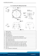
The clamping force block has four hydraulic connections:
I, II, III,
IV
.
Two connections for OPEN (
I
and
III
) and two connections for
CLOSE (
II
and
IV
).
Which of the two hydraulic connections has to be opened for
actuation depends on the specific application:
• Connection
I
and
II
for operation with external hydraulic pipes
or hose lines.
The threads for the hydraulic fittings – on the front of the
housing (item 1) – are for all G
1
/
8
" clamping force blocks.
• Connection
III
and
IV
in the base for hose-free direct
connection in the machine table.
The threads for hose-free, direct connection are not designed for
hydraulic screw fittings.
NOTE:
With the delivery of the clamping force block, all four hydraulic
connections are sealed. On the base side with set-screws (item 60)
and on the front with locking screws (item 23).
• When using the air purge via connection 5, the sound absorber
(V) must be removed and replaced by a set-screw (item
93).
The clamping force block has two more base connections (
6/7
) for
direct lubrication through the machine table. These connections
come sealed on delivery with set-screws (item 62).
Dynamic pressure monitoring of the jaw end positions (variant
"PM")
Dynamic pressure monitoring for the jaw end positions is
integrated via connections 1 and 4 on the bottom.
Connection 1
→ monitoring open jaw position.
Connection 4 → monitoring closed jaw position.
The max. pressure for the monitoring functions is 2 bar.
Limit volumetric flow to 10 l/min.
Pressure difference between stroke end positions min. 1 bar.
5.2.1
5.2.2

