SCHUNK ROTA EP 380-127 Assembly And Operating Manual Download Page 30


30 

02.00|0889073_ROTA TB-TBS-EP |en 


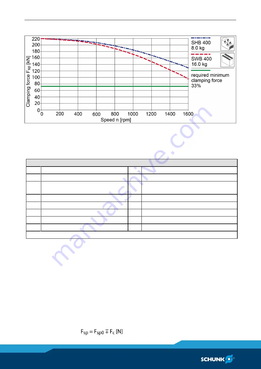
Clamping force-RPM-diagram ROTA EP-LH 460-185


Calculations for clamping force and speed 

Missing information or specifications can be requested from the 

manufacturer.


Legend 

F

c


Total centrifugal force [N] 

M

cAB

  Centrifugal torque of top jaws [Kgm] 

F

sp

  Effective clamping force [N] 

M

cGB

  Centrifugal torque of base jaws [Kgm] 

F

spmin

  minimum required clamping force 

[N] 

Speed of rotation [RPM] 

F

sp0

  Initial clamping force [N] 

r

s


Center of gravity radius [mm] 

F

spz

  Cutting force [N] 

r

sAB

  Center of gravity radius of top jaw [mm] 

m

AB

  Mass of one top jaw [kg] 

s

sp

  Safety factor for clamping force 

m

B

  Mass of chuck jaw set [kg] 

s

z


Safety factor for machining 

M

c

  Centrifugal torque [kgm] 

Σ

s


Max. clamping force of lathe chuck [N] 

kgm × 9.81 = Nm  


Calculation of the required clamping force in case of a given rpm 

The 

initial clamping force F

sp0

 is the total force impacting radially 

on the workpiece via the jaws due to actuation of the lathe chuck 

during shutdown. Under the influence of rotation, the jaw mass 

generates an additional centrifugal force. The centrifugal force 

reduces or increases the initial clamping force depending on 

whether gripping is from the outside inwards or from the inside 

outwards.  

The sum of the initial clamping force 

F

sp0

 and the 

total centrifugal 

force F

c

 is 

the effective clamping force F

sp


6.3 

6.3.1 

Summary of Contents for ROTA EP 380-127

Page 1: ...Translation of Original Operating Manual Pneumatic power chuck ROTA TB TBS EP Assembly and Operating Manual Superior Clamping and Gripping ...

Page 2: ...ons for the purpose of technical improvement Document number 0889073 Version 02 00 27 02 2020 en H D SCHUNK GmbH Co All rights reserved Dear Customer thank you for trusting our products and our family owned company the leading technology supplier of robots and production machines Our team is always available to answer any questions on this product and other solutions Ask us questions and challenge...

Page 3: ...ta 17 6 2 Clamping force speed diagrams 20 6 3 Calculations for clamping force and speed 30 6 3 1 Calculation of the required clamping force in case of a given rpm 30 6 3 2 Calculation example required initial clamping force for a given speed 32 6 3 3 Calculation of the permissible speed in case of a given initial clamping force 34 6 4 Grades of Accuracy 35 6 5 Permissible imbalance DIN ISO 21940 ...

Page 4: ...850 TB TB LH 1000 year of construction 2010 or later 54 10 1 1 Disassembly 54 10 1 2 Assembly 55 10 2 All TB TB LH up to size 1000 until year of construction 2009 and all EP EP LH 56 10 2 1 Disassembly 56 10 2 2 Assembly 58 11 Control of types TB TB LH EP EP LH 59 12 TBS TBS LH stationary power chucks 59 13 Power Chuck with extended and standard jaw stroke LH 60 14 Disposal 61 15 Spare parts 62 16...

Page 5: ...al Illustrations in this manual are provided for basic understanding and may differ from the actual product design In addition to these instructions the documents listed under 1 2 Page 6 are applicable Presentation of Warning Labels To make risks clear the following signal words and symbols are used for safety notes DANGER Danger for persons Non observance will inevitably cause irreversible injury...

Page 6: ...able documents General terms of business Catalog data sheet of the purchased product Calculation of the jaw centrifugal forces Technology chapter in the lathe chuck catalog The documents marked with an asterisk can be downloaded on our homepage schunk com 1 2 ...

Page 7: ...e also means that the user has read and understood this operating manual in its entirety especially the chapter Basic safety notes The maximum RPM of the chuck and the required clamping force must be determined by the user for the respective clamping task based on the applicable standards and technical specifications of the manufacturer See also Calculations for clamping force and RPM in the chapt...

Page 8: ...e chuck s clamping force may fail immediately and the workpiece may be released in an uncontrolled manner This poses a risk of death or injury to the operating personnel and can result in serious damage to the automated system The machine manufacturer and the operator of the machine must carry out and document a hazard assessment and risk analysis to ensure that suitable measures are taken to main...

Page 9: ...erating personnel from clothing or hair being caught on the lathe chuck and being dragged into the machine Loose clothing or long hair may become caught on projecting parts of the lathe chuck and be drawn into the machine The machines and equipment must fulfill the minimum requirements of the EC Machinery Directive specifically they must have effective technical measures to protect against potenti...

Page 10: ...ts Do not reach between the jaws Wear safety gloves Observe the safety and accident prevention regulations during operation of the chuck especially in connection with machining centers and other technical equipment CAUTION Risk of burns due to workpieces with high temperatures Wear protective gloves when removing the workpieces Automatic loading is preferred CAUTION Risk of damages due to incorrec...

Page 11: ...e clamping energy fails the workpiece must remain firmly clamped until the spindle is shut down and the workpiece is secured The technical safety requirements in the respective operating instructions must be observed exactly Functional test After installation of the chuck its function must be checked prior to start up Two important points are Clamping force At max actuating force pressure the clam...

Page 12: ...SCHUNK lathe chuck catalog or contact SCHUNK Use a suitable high pressure grease gun to ensure that you reach all the greasing areas To ensure correct distribution of the grease move the clamping piston to its end positions several times lubricate again and then check the clamping force We recommend checking the clamping force using a clamping force tester before starting a new production run and ...

Page 13: ...g instructions specified by the manufacturer must be complied with to ensure safe operation of the chuck Work must be carried out by qualified specialist personnel with the relevant safety training Use of special chuck jaws When using special chuck jaws please observe the following rules The chuck jaws should be designed to be as light and as low as possible The clamping point must be as close as ...

Page 14: ... have access to the operating manual especially the chapter Fundamental safety instructions We recommend that the operator create in house safety operating instructions Persons in training may be assigned to machines and technical equipment in which a chuck is mounted only if they are under the constant guidance and supervision of qualified specialists Organizational measures Obeying the rules Via...

Page 15: ...ault has been located and remedied Only allow specialists to remedy faults Spare parts Only ever use original SCHUNK spare parts Environmental regulations Comply with the applicable legal norms when disposing of waste Using personal protective equipment When using this product you must comply with the relevant health and safety at work rules and you must use the required personal safety equipment ...

Page 16: ... and wear parts are not included in the warranty Torques per screw Tightening torques for mounting screws used to clamp the chuck on lathes or other suitable technical equipment screw quality 10 9 Screw size M6 M8 M10 M12 M14 M16 M18 M20 M22 M24 M27 M30 Admissible torque MA Nm 13 28 50 88 120 160 200 290 400 500 1050 1500 Tightening torques for mounting screws used to attach top jaws onto the chuc...

Page 17: ...Serration of the jaws mm 3 32 x 90 Distributor ring Ø mm 467 467 470 570 570 570 570 685 Centrifugal torque of base jaw kgm McGB 0 497 0 535 0 626 0 749 0 847 0 891 1 300 1 624 Max jaw eccentricity of center of gravity in axial direction mm amax 36 ROTA TB Size 630 310 630 330 800 365 800 410 1000 534 400 140 LH 470 185 LH 500 205 LH Chuck Ø 662 685 800 800 1000 467 470 570 Chuck through bore mm 3...

Page 18: ...TA TB Size 500 230 LH 600 275 LH 630 265 LH 630 325 LH 850 375 LH 1000 560 LH 1200 640 LH Chuck Ø 570 610 685 720 850 1000 1200 Chuck through bore mm 230 275 265 325 375 560 640 Max clamping force kN 220 180 330 280 330 170 170 Max rotation speed min 1 1100 1100 900 900 750 450 180 Stroke per jaw mm 25 4 25 4 38 25 4 25 4 25 4 38 Serration of the jaws mm 3 32 x 90 Distributor ring Ø mm 570 570 685...

Page 19: ... the chuck WARNING Risk of personal injury and property damage due to parts flying off in the event of a screw breakage on unhardened top jaws Soft standard top jaws must be hardened in the countersink region They should only be depth hardened not surface hardened If unhardened top jaws or chuck jaws in a special design are used ensure that the jaws weigh as little as possible For soft top jaws or...

Page 20: ...ith the base jaw outer edge The chuck is in perfect condition and lubricated with SCHUNK LINO MAX special grease Should one or several of the above mentioned parameters be changed the diagrams are no longer valid Chuck set up for clamping force speed diagram F 3 Clamping force per jaw S Center of gravity rs Center of gravity radius amax Max jaw eccentricity of center of gravity in axial direction ...

Page 21: ...02 00 0889073_ROTA TB TBS EP en 21 Clamping force RPM diagram ROTA TB 400 140 Clamping force RPM diagram ROTA TB 470 185 Clamping force RPM diagram ROTA TB 500 160 ...

Page 22: ...22 02 00 0889073_ROTA TB TBS EP en Clamping force RPM diagram ROTA TB 500 205 Clamping force RPM diagram ROTA TB 500 230 Clamping force RPM diagram ROTA TB 600 275 ...

Page 23: ...02 00 0889073_ROTA TB TBS EP en 23 Clamping force RPM diagram ROTA TB 630 265 Clamping force RPM diagram ROTA TB 630 310 Clamping force RPM diagram ROTA TB 630 330 ...

Page 24: ...24 02 00 0889073_ROTA TB TBS EP en Clamping force RPM diagram ROTA TB 800 365 Clamping force RPM diagram ROTA TB 800 410 Clamping force RPM diagram ROTA TB 1000 534 ...

Page 25: ...02 00 0889073_ROTA TB TBS EP en 25 Clamping force RPM diagram ROTA TB LH 400 140 Clamping force RPM diagram ROTA TB LH 470 185 Clamping force RPM diagram ROTA TB LH 500 205 ...

Page 26: ...26 02 00 0889073_ROTA TB TBS EP en Clamping force RPM diagram ROTA TB LH 500 230 Clamping force RPM diagram ROTA TB LH 600 275 Clamping force RPM diagram ROTA TB LH 630 265 ...

Page 27: ...02 00 0889073_ROTA TB TBS EP en 27 Clamping force RPM diagram ROTA TB LH 630 325 Clamping force RPM diagram ROTA TB LH 850 375 Clamping force RPM diagram ROTA TB LH 1000 560 ...

Page 28: ...28 02 00 0889073_ROTA TB TBS EP en Clamping force RPM diagram ROTA TB LH 1200 640 Clamping force RPM diagram ROTA EP 380 127 Clamping force RPM diagram ROTA EP 460 165 ...

Page 29: ...02 00 0889073_ROTA TB TBS EP en 29 Clamping force RPM diagram ROTA EP 460 185 Clamping force RPM diagram ROTA EP 500 260 Clamping force RPM diagram ROTA EP LH 460 165 ...

Page 30: ...w kg ssp Safety factor for clamping force mB Mass of chuck jaw set kg sz Safety factor for machining Mc Centrifugal torque kgm Σs Max clamping force of lathe chuck N kgm 9 81 Nm Calculation of the required clamping force in case of a given rpm The initial clamping force Fsp0 is the total force impacting radially on the workpiece via the jaws due to actuation of the lathe chuck during shutdown Unde...

Page 31: ...ing force Fspmin Consequently the workpiece is released spontaneously Do not exceed the calculated RPM Do not fall below the necessary minimum clamping force Reduction in effective clamping force by the magnitude of the total centrifugal force for gripping from the outside inwards The required effective clamping force for machining Fsp is calculated from the product of the machining force FspZ and...

Page 32: ...um of 67 of the initial clamping force The formula for the calculation of the total centrifugal force Fc is For this n is the given speed of rotation in RPM The product mB rs is referred to as the centrifugal torque Mc In case of toolholders with split chuck jaws i e with base jaws and top jaws for which the base jaws change their radial position only by the stroke amount the centrifugal torque of...

Page 33: ...ews and T nuts are not taken into account First the required effective clamping force Fsp is calculated using the machining force stated Initial clamping force during shutdown Calculation of total centrifugal force For two part chuck jaws the following applies Take the centrifugal torque of the base jaw and top jaw specified from the Lathe chuck data table For the centrifugal torque of the top jaw...

Page 34: ... Permissible RPM for a given effective clamping force The following data is known from previous calculations Initial clamping force during shutdown Fsp0 17723 N Machining force for machining job Fspz 3000 N application specific Total centrifugal torque of all jaws Mc 2 668 kgm Safety factor Sz 1 5 according to VDI 3106 Safety factor Ssp 1 5 according to VDI 3106 NOTE Masses of the jaw mounting scr...

Page 35: ...orresponds to the balancing quality class 6 3 according to DIN ISO 21940 11 Residual imbalance risks may arise due to insufficient rotation compensation being achieved see DIN EN 1550 6 2 e This applies particularly to high speeds asymmetrical workpieces or the use of various top jaws as well as uneven application of lubricants In order to prevent damage resulting from these residual risks the ent...

Page 36: ...pindle nose and ready machined intermediate flange for radial and axial run out The permissible limit is 0 005 mm in accordance with DIN 6386 and ISO 3089 2 The contact surface must be chamfered and completely clean at the bore holes Distributor ring The distributor ring is a component that is completely separate from the chuck and is centered and retained on the headstock of the lathe axially and...

Page 37: ... ring If the headstock face surface is machined the calculated dimension can be taken as the height dimension for the spacing console If the end face of the headstock is unmachined the height dimension should be calculated by adding together the individual distances then subtracting 4 5 mm In accordance with the sketch overleaf the spacing console comprises two shells and is made of suitable steel...

Page 38: ...n be centrally aligned with the chuck using a ruler for complete accuracy then screwed onto it CAUTION The distributor ring must be aligned with the outer chuck diameter in such a way that a radial and axial run out tolerance of at least 0 1 mm is achieved When detaching the chuck from the spindle nose the spacing console remains attached to the distributor ring and is only detached from the heads...

Page 39: ...onto this collar using two screws The height of the clamping ring is configured as described in the previous chapter 7 2 1 Page 37 During assembly this two piece clamping ring is first screwed to the threads of the distributor ring Once this is done the entire assembly group is clamped onto the rigid collar of the machine When mounting the chuck with a bayonet or Camlock the clamping ring should h...

Page 40: ...uction 2010 or later For power chuck types TB and TB LH in size 400 850 a chuck flange is mounted on the spindle nose 12 M12 M16 or M24 hexagon socket screws for TB 400 9 x 40 are used to screw the chuck onto the chuck flange by the front face side The cylindrical recess on the flange must protrude 1 mm from the floor of the 7 3 7 3 1 ...

Page 41: ... can be used to mount the pneumatic chuck on spindles in accordance with DIN 55026 DIN 55027 and DIN 55029 TB and TB LH 400 850 1 Labyrinth gap 1 5 mm 9 Locking screw 2 Lubricating nipple 10 Pilot controlled check valve 3 Base jaw 11 Pneumatic connection 4 Hexagon socket screw 12 Chuck mount 5 T nut 13 Piston cover 6 Guide bushing 14 Sealing disk 7 Chuck body 15 Profile seal 8 Piston 16 Distributo...

Page 42: ...er is then screwed onto the spindle nose chuck flange and the bore holes are sealed using DIN 908 locking screws and copper sealing rings In order to simplify the mounting procedure the bushing is removed from the chuck body The chuck body cannot be screwed onto the cylinder until this is done When doing this pay attention to the three O rings used to seal the channel bore holes taking care to ens...

Page 43: ...8 Screw for mounting cylinder on flange or spindle 9 Guide bushing 19 DIN 908 locking screw and copper seal 10 Piston 20 Profile seal In order to prevent the chuck from being subjected to greater loads the centering mount can be replaced with one that has a short taper and is suitable for direct mounting on the spindle nose using a bayonet DIN 55027 or Camlock DIN 55029 The inner and outer O rings...

Page 44: ...iggers the piston stroke and the base jaws are moved by the wedge hook The valve system blocks and stores the pressure in the chuck body while the profile seals due to their elasticity are raised from the chuck body by the ventilation of the supply lines and therefore are not subject to wear from the rotating chuck Air transmission system Air transfer takes place only when the headstock spindle is...

Page 45: ...ty and is not subjected to wear during rotation of the chuck The off and return air out of the opposit cylinder chamber leaves for the most part directly below the associated profile sealing CAUTION During actuation of the clamping device clamping or releasing it must be ensured that a short ventilation time is maintained between the switching processes This ventilation time must last at least 0 5...

Page 46: ...o the profile seals through the two blocking pistons The change of the air flow at the profile seals causes the air channel to one cylinder chamber release chamber to be ventilated The reversal of compressed air from one cylinder chamber to another is caused by the axial movement of the valve body while the two single blocking or non return pistons execute only one stroke during blocking of their ...

Page 47: ...he two sided extended and self locking 10 wedge slant standard wedge hook or base jaw The clamping forces are absorbed by the diameter of the piston collar and braced against by the chuck body Both sides of a piston cover screwed onto the piston neck for clamping and unclamping are pressurized thus causing the piston cover to trigger the axial motion of the piston 8 4 ...

Page 48: ...d blocks the pressure from the outside It is very important that the bore hole of the valve system be lightly lubricated with oil so that the valve system can move easily Too much grease lubrication and dirt in the valve bore hole will significantly impair the function of the chuck and should be avoided CAUTION When actuating the clamping device clamping or releasing allow a short pause for ventil...

Page 49: ... must be checked daily and oil must be added if necessary If the oil consumption is too low i e if the oil level does not visibly drop over a period of 2 to 3 days the oil adjustment screw must be opened slightly Depending on how much condensation is accumulated the condensation drain screw should be opened occasionally 2 part maintenance unit WEH type with filter oiler and pressure control valve ...

Page 50: ...ective metal cage with transparent polycarbonate tank 9 Pressure gauge Ø 40 4 Fill level indicator for condensate small inspection window 10 Protective cage lock 5 Fill level indicator for oil min max large inspection window 11 Distributor module as accessory with two connections Ø T at front and rear and one ready fitted seal plug 6 Semi automatic condensate drain G 1 8 connection Ø W G 1 4 D 84 ...

Page 51: ...1 liters 10 approx 2 4 approx 24 mm3 Flow rate characteristic curves and pressure drops Cleaning and lubrication of the chuck The chuck s accuracy life span and ability to maintain an even clamping force depend greatly on regular cleaning and sufficient lubrication Rust scale casting dust and chips produce friction and reduce motion As such the chuck must be lubricated with LINOMAX special grease ...

Page 52: ... disassembled cleaned and lubricated and the sealing rings replaced if necessary The time for which the chuck can be used before full maintenance is required depends on the level of dirt it accumulates and the clamping frequency As such it is not possible to specify a generally applicable rule for this Maintenance intervals Lubrication of the grease areas Lubrication interval Strain every 25 hours...

Page 53: ...the same clamping position and under the same operating pressure as are used for machining the workpiece When doing this it is important to ensure that all the mounting screws are screwed in tightly and evenly The fine serration of the base jaws and top jaws should always be cleaned especially when the top jaws are adjusted otherwise the run out accuracy will be impaired Hardened reversible jaws a...

Page 54: ...ully unscrew the locking screw 15 and remove the pilot controlled non return valve system and O ring 37 CAUTION Pressure in the chuck The valve system 13 must be removed before proceeding with disassembly 4 Check all the O rings in the valve system for wear and replace them if necessary 5 Unscrew the hexagon socket screws 23 from the chuck mount 7 then screw 3 of them into the threaded extraction ...

Page 55: ... the base jaws 2 in the corresponding guides to achieve the same run out accuracy NOTE The piston wedge hook with the dot marking on the inside is aligned using jaw guide 1 2 Allow the piston with the O rings 40 to snap into the base jaw wedge hooks 2 and push it in up to the end of the stroke 3 Insert the O ring 43 and sealing disk 5 with O ring 42 and screw them into the chuck body securely and ...

Page 56: ...sure in the chuck The valve system 13 must be removed before proceeding with disassembly 4 Check all the O rings in the valve system for wear and replace them if necessary 5 Unscrew the screws 24 in the chuck and extract the bushing 4 from the chuck body using the extraction threads Disassemble the bushing completely 6 Use the supplied eye bolt thread on circumference to secure the chuck body part...

Page 57: ...disk 5 can now be removed from the chuck On all EP chucks the cylindrical screws with copper sealing rings 23 and 48 must first be unscrewed Remove the O rings 38 and 39 check for wear and renew if necessary 14 Pull the piston 3 out of the chuck body using the screws Remove the O ring 37 check for wear and renew if necessary 15 Secure the whole chuck body to a cargo crane with the eye bolt on the ...

Page 58: ...nd tighten the cylindrical screws 22 evenly 5 Insert the O ring 35 6 Before inserting the profile ring seals 47 in the slots in the distributor ring rub them with grease by hand so that they remain elastic There must be no visible grease residue When re inserting the profile ring seals 47 ensure the that air passage openings do not overlap with the pneumatic connections on the distributor ring 7 M...

Page 59: ...ck is available consisting of a pressure control valve a pressure switch 2 magnetic valves with automatic clamping time monitoring including 2 sensors and 2 analysis units A maintenance unit consisting of a filter water separator and oiler must be installed upstream of this control block TBS TBS LH stationary power chucks CAUTION No distributor ring no check valve always continuous pressure The op...

Page 60: ...rie are not allowed to be used for I D clamping Moreover no workpieces are allowed to be clamped on the fast jaw stroke since due to the long jaw strokes the resulting clamping forces are lower 1 Please make sure that the entire fast stroke plus at least 1 3 of the clamping stroke corresponding to the basic covering of the TB LH lathe chuck is executed during workpiece clamping 2 13 ...

Page 61: ...lect the escaping liquids and dispose of them properly in line with the statutory provisions Remove any identifiable plastic or aluminum parts installed in or on the chuck and dispose of them properly in line with the statutory provisions Dispose of the chuck s metal parts as scrap metal Alternatively you can return the chuck to SCHUNK for proper disposal 14 ...

Page 62: ...tion 1 Chuck body 2 base jaw 3 Piston 4 Sleeve 5 Sealing disk 6 Piston cover 7 Cylinder mount 8 Distributor ring 9 T nuts 13 double check valve 15 Locking screw 16 Filler plug 19 Screw DIN EN ISO 4762 10 9 20 Screw DIN 7984 10 9 21 Screw DIN 7984 10 9 23 Screw DIN EN ISO 4762 10 9 24 Screw DIN EN ISO 4762 10 9 25 Screw DIN EN ISO 4762 10 9 26 funnel lubrication nipple 37 O ring DIN 3771 39 O ring ...

Page 63: ...valve 15 Locking screw 16 Filler plug 19 Screw DIN EN ISO 4762 10 9 22 Screw DIN EN ISO 4762 10 9 23 Screw DIN EN ISO 4762 10 9 24 Screw DIN EN ISO 4762 10 9 25 Screw DIN EN ISO 4762 10 9 28 Funnel or Hydraulic type lubrication nipple 35 O ring 36 O ring 37 O ring 38 O ring 39 O ring 40 O ring 41 O ring 42 O ring 45 O ring 46 Copper sealing ring DIN 7603 48 Copper sealing ring DIN 7603 49 Profile ...

Page 64: ...Assembly drawings 64 02 00 0889073_ROTA TB TBS EP en Assembly drawings TB 400 850 16 ...

Page 65: ...Assembly drawings 02 00 0889073_ROTA TB TBS EP en 65 TB 400 850 LH Item for TB 400 115 and TB 400 140 ...

Page 66: ...Assembly drawings 66 02 00 0889073_ROTA TB TBS EP en TB 400 850 LH ...

Page 67: ...Assembly drawings 02 00 0889073_ROTA TB TBS EP en 67 X Clamping stroke TB 1000 LH ...

Page 68: ...Assembly drawings 68 02 00 0889073_ROTA TB TBS EP en ...

Page 69: ...Assembly drawings 02 00 0889073_ROTA TB TBS EP en 69 EP LH ...

Page 70: ...Assembly drawings 70 02 00 0889073_ROTA TB TBS EP en ...

Page 71: ...818015 0818016 0818019 0818051 0818125 0818026 0818135 0818141 0818014 0818035 0818003 0818006 0818007 0818052 0818008 0818009 0818023 0818018 The partly completed machine may not be put into operation until conformity of the machine into which the partly completed machine is to be installed with the provisions of the Machinery Directive 2006 42 EC is confirmed Applied harmonized standards especia...

Page 72: ... 0818018 To be provided by the System Integrator for the overall machine Fulfilled for the scope of the partly completed machine Not relevant 1 1 Essential Requirements 1 1 1 Definitions X 1 1 2 Principles of safety integration X 1 1 3 Materials and products X 1 1 4 Lighting X 1 1 5 Design of machinery to facilitate its handling X 1 1 6 Ergonomics X 1 1 7 Operating positions X 1 1 8 Seating X 1 2 ...

Page 73: ...6 5 Cleaning of internal parts X 1 7 Information 1 7 1 Information and warnings on the machinery X 1 7 1 1 Information and information devices X 1 7 1 2 Warning devices X 1 7 2 Warning of residual risks X 1 7 3 Marking of machinery X 1 7 4 Instructions X 1 7 4 1 General principles for the drafting of instructions X 1 7 4 2 Contents of the instructions X 1 7 4 3 Sales literature X The classificatio...

Reviews: