


Assembly
08.00 | PRG | Assembly and Operating Manual | en | 389325
25
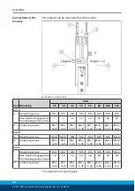
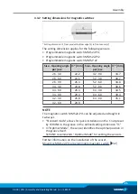
4.3.2 Setting dimensions for magnetic switches
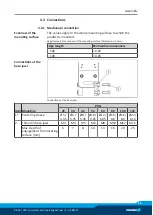
* Setting dimension I1, from product bottom edge (1) to front sensor (2)
The setting dimension applies for the following sensors:
• Programmable magnetic switch MMS 22-PI1
• Programmable magnetic switch MMS 22-PI2
• Programmable magnetic switch MMS-P 22
Size - Opening angle
per jaw
l1* [mm] Size - Opening angle
per jaw
l1* [mm]
26 - 30
22.2
42 - 90
33.7
26 - 60
24.1
52 - 30
30.7
26 - 90
26.4
52 - 60
34.8
34 - 30
23.8
52 - 90
39.6
34 - 60
26.3
64 - 30
34.5
34 - 90
29.3
64 - 60
39.4
42 - 30
26.8
64 - 90
45.1
42 - 60
29.9
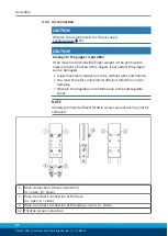
NOTE
The magnetic switch MMS 22-PI1 can be adjusted and taught in
two ways.
• "Standard mode" allows for quick installation on the T-nut preset
by SCHUNK in the groove or the defined setting dimension "l1."
• In "Optimal Mode", the sensor identifies the optimal position in
the groove itself.
SCHUNK recommends "Optimal Mode" for setting the sensors.
Further information on the installation of the sensor,


