Handling and operation
06.00 | PPU-P | Assembly and Operating Manual | en | 389323
43
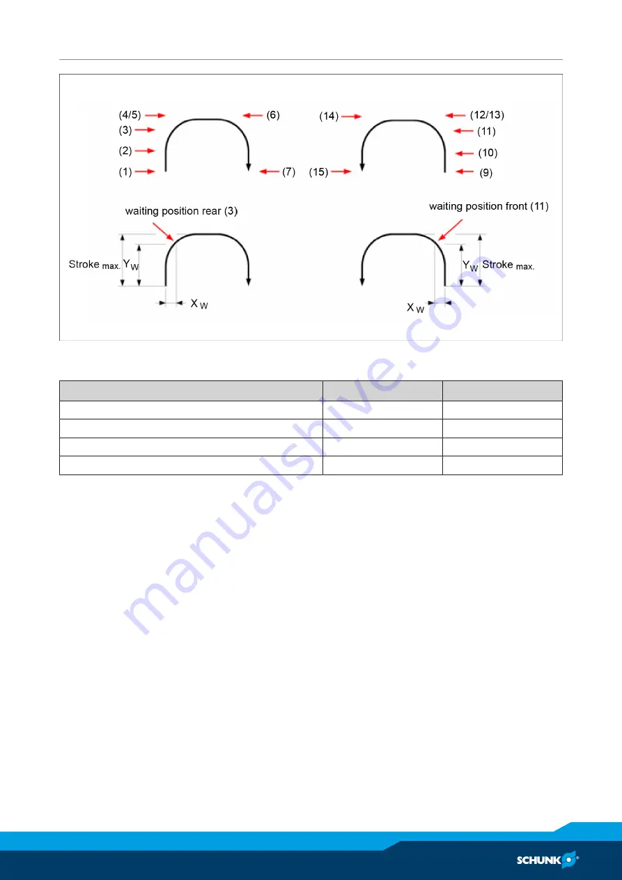
Flow diagram for actuation of stand-by position, stand-by position range
Stand-by position range
Designation
PPU-P 10
PPU-P 30
Stroke
max
[mm]
45
60
X
W max.
at rest [mm]
17.5
25
X
W max.
Overshoot upon actuation [mm]
35
50
Y
W min.
[mm]
32.5
50
Description of
actuation of back
stand-by position
PPU-P in back end position / home position:
• Horizontal: Cantilever arm retracted pressurized connection: (C)
• Vertical: Cantilever arm lowered pressurized connection: (B)
• Sensor allocation: (VE)
Ø
PPU-P in back end position Actuation of valve B → A (lower → raise)
Move to back stand-by position
Cantilever arm moves vertically upward
Ø
Sensor reaches switching point UH
Maintain actuation of both valves:
To move to the stand-by position the signal of the sensor
UH is ignored
By overshooting, sensor UV is also reached briefly – ignore this
signal also!
Cantilever arm continues moving vertically only, then upward
on curve radius
Ø
The back stand-by position is reached


