background image

General 


02.00|NSL3 turn 450-3, 450-3-Z, 570-5, 570-5-Z |en 


Applicable documents 


   General terms of business* 


  Catalog data sheets of standard products used * 


  Assembly and Operating Manual for VERO-S quick-change 

pallet system NSE3, NSE-T3 


  Assembly and Operating Manual for manual lathe chuck used * 

The documents marked with an asterisk (*) can be downloaded on 
our homepage 

schunk.com


Sizes 

This operating manual applies to the following sizes: 


  NSL3 turn 450-3, NSL3 turn 450-3-Z 


  NSL3 turn 570-5, NSL3 turn 570-5-Z 


Warranty 

The warranty period is 12 months after delivery date from factory 
or 500 000 cycles*, if it is used as intended, under the following 
conditions: 


  Observe the applicable documents,  

(

 1.1.2, Page 6)


  Observe the ambient conditions and operating conditions, 

(

 2.5, Page 11)


  Observance of the specified care and maintenance instructions 

(

 6, Page 42)


Parts touching the workpiece and wear parts are not included in 
the warranty. 

* A cycle consists of a complete clamping process ("Open" and 
"Close"). 

1.1.2 

1.1.3 

1.2 

Summary of Contents for NSL3 turn 450-3

Page 1: ...Translation of the assembly and operating manual VERO S Clamping Station NSL3 turn 450 3 450 3 Z 570 5 570 5 Z Assembly and Operating Manual Superior Clamping and Gripping...

Page 2: ...family owned company the leading technology supplier of robots and production machines Our team is always available to answer any questions on this product and other solutions Ask us questions and cha...

Page 3: ...al protective equipment 12 2 8 Notes on safe operation 13 2 9 Transport 13 2 10 Malfunctions 13 2 11 Disposal 14 2 12 Fundamental dangers 14 2 12 1 Holding force and screw strength 15 2 12 2 Protectio...

Page 4: ...etup 38 5 Function 40 5 1 Functioning principle of the flexible centering cone 40 6 Maintenance and care 42 6 1 Disassembly and assembly 42 6 2 Removal and installation of the centering cone 43 6 3 Fu...

Page 5: ...nual Illustrations in this manual are provided for basic understanding and may differ from the actual product design In addition to these instructions the documents listed under 1 1 2 Page 6 are appli...

Page 6: ...ual applies to the following sizes NSL3 turn 450 3 NSL3 turn 450 3 Z NSL3 turn 570 5 NSL3 turn 570 5 Z Warranty The warranty period is 12 months after delivery date from factory or 500 000 cycles if i...

Page 7: ...e 2 Nut for T slot 8 Flexible centering taper centering element for Z version 3 Guide pin for table groove 9 Mounting screws for star groove tables in pitch circle 8 x 45 4 Fitting bore for centering...

Page 8: ...ect the central bore fitted Accessory pack 1 centering pin 50 mm tolerance class g6 2 guide pins for groove 14 12 screws DIN ISO 4762 M12 x 50 mm 12 nuts for T slot DIN 508 M12 x 14 1 locking coupling...

Page 9: ...2 x 14 1 locking coupling G1 8 4 eye bolts M12 DIN 580 1 eye bolt M16 DIN 580 Assembly and Operating Manual Accessories see catalog or data sheets when ordering separately Clamping pallets with a cent...

Page 10: ...lamping points are designed for use with manual chucks up to size 315 Clamping stations with at least five clamping points are designed for use with manual chucks up to size 630 The product may only b...

Page 11: ...ting conditions can make the product unsafe leading to the risk of serious injuries considerable material damage and or a significant reduction to the product s life span Make sure that the product is...

Page 12: ...ervice personnel of the manufacturer is able to perform the delegated tasks and to recognize and avoid possible dangers Personal protective equipment Use of personal protective equipment Personal prot...

Page 13: ...ce instructions Observe the current safety accident prevention and environmental protection regulations regarding the product s application field Transport Handling during transport Incorrect handling...

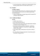
Page 14: ...Follow local regulations on dispatching product components for recycling or proper disposal Fundamental dangers General Observe safety distances Never deactivate safety devices Before commissioning th...

Page 15: ...r the product s safety and cause serious injuries and considerable material damage Have all work carried out by appropriately qualified personnel For all work secure the product against accidental ope...

Page 16: ...ontrol unit and the current operating condition of the drive Perform maintenance work modifications and attachments outside the danger zone defined by the movement range To avoid accidents and or mate...

Page 17: ...evice or pallet falling down Use suitable lifting equipment and means of transport During horizontal or overhead applications the device or pallet must be secured before loosening to prevent it from f...

Page 18: ...g spring force Risk of injury due to parts automatically moving to their end positions following actuation of an emergency stop or after switching off the power supply Wait for the system to shut down...

Page 19: ...peration CAUTION Risk of injury due to impurities e g metal chips in the exhaust and air purge connections of the clamping station The danger zone must be surrounded by a protective enclosure during o...

Page 20: ...the safety and accident prevention regulations when operating the quick change pallet system especially when working with machine tools and other technical equipment CAUTION Risk of burns due to work...

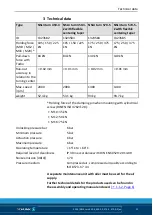
Page 21: ...000 2000 1400 1400 weight 52 4 kg 53 1 kg 93 kg 93 7 kg Holding force of the clamping pin when mounting with cylindrical screw DIN EN ISO 4762 12 9 M10 35 kN M12 50 kN M16 75 kN Unlocking pressure bar...

Page 22: ...e bolts must be removed before commissioning the clamping station General assembly notes When connecting the clamping station ensure that it is possible to completely bleed the piston chamber during t...

Page 23: ...e required tightening torques can be found in the table at the end of the chapter The central alignment on the machine table is carried out using the centering bolt in the turning center of the clampi...

Page 24: ...Nm 13 28 50 88 120 160 200 290 400 500 Connections of the clamping station Connections on the clamping station 1 Actuation of unlocking connection 5 Sealing nipple NW 5 2 Pressure display for operati...

Page 25: ...use parts workpieces to come loose and be expelled The clamping station may only be operated with the installed sealing nipples Unlocking connection If the unlocking connection of the clamping station...

Page 26: ...n 4 3 Page 24 When the clamping system is pressurized with compressed air via the unlocking connection all of the clamping modules are unlocked The indicator pin on the pressure display drops to the u...

Page 27: ...cy and supporting effect When the clamping pin is fitted with positioning accuracy in a direction SPB 40 pay attention to the angle oriented positioning of the sword shaped alignment surfaces The supp...

Page 28: ...quick change pallet modules 1 Clamping area for Type A clamping pin SPA with positioning accuracy 2 Clamping area for Type B clamping pin SPB for positioning in one direction 3 Clamping area for Type...

Page 29: ...es NSL3 turn with 5 VERO S quick change pallet modules 1 Clamping area for Type A clamping pin SPA with positioning accuracy 2 Clamping area for Type B clamping pin SPB for positioning in one directio...

Page 30: ...RO S quick change pallet module the clamping pin is fitted with positioning accuracy in a direction SPB 40 which ensures the angular alignment of the clamping pallet Attention must be paid to the angl...

Page 31: ...nd centering taper in the turning center 1 Centering taper flexible for highest positioning accuracy replaces Type A SPA clamping pin 2 Clamping area for Type B clamping pin SPB for positioning in one...

Page 32: ...NSL3 turn with 5 VERO S quick change pallet modules and centering taper in the turning center 1 Centering taper flexible for highest positioning accuracy replaces Type A SPA clamping pin 2 Clamping a...

Page 33: ...eaded holes or a sufficiently thick mounting material If clamping pins are used outside of SCHUNK pallets for example in customer specific devices or workpieces the outer diameter of the part to be cl...

Page 34: ...f the fitted SPA 40 With several clamping positions of a clamping pallet without centering taper in the turning center all three types of clamping pins can be replaced with the SPG 40 The repeat accur...

Page 35: ...n 2 Type C clamping pin SPC with centering clearance of 0 1 mm 3 Type A clamping pin SPA with positioning accuracy 4 Pitch circle Clamping pallet with five clamping points for clamping station NSL3 tu...

Page 36: ...est positioning accuracy replaces Type A clamping pin 3 Type C clamping pin SPC with centering clearance of 0 1 mm 4 Pitch circle Clamping pallet with five clamping points for clamping station NSL3 tu...

Page 37: ...Accessories for Clamping Pallets 8 Page 47 Based on Fig Installation example for centering sleeve in clamping pallet the installation of the centering sleeve can be made in house Installation example...

Page 38: ...he taper connection against penetrating dirt CAUTION To protect the quick change pallet modules the clamping pallet must cover them completely Clamping pallet setup NSL3 turn Z in loading position NSL...

Page 39: ...o the turbo connection and apply a short turbo impulse Once this is done disconnect the air connection from the clamping station The clamping pallet is locked and aligned with the VERO S clamping modu...

Page 40: ...m with the required system pressure Functioning principle of the flexible centering cone By means of the centering taper built in the turning center the highest repeat accuracy is achieved based on th...

Page 41: ...h maximum centering accuracy A transition fit ensures that the seat of the taper is installed free from play in the turning center of the base plate item 1 With a centering taper the alignment functio...

Page 42: ...ute the air to the clamping modules To disassemble first unscrew the screws item 9 and then the set screws item 18 2 Alternately screw lifting screws into the threads of the set screws item 18 and eve...

Page 43: ...highest possible accuracy it must be mounted in the same installation position again When disassembling make sure that the taper surface does not become damaged If the clamping station is used without...

Page 44: ...clamping system shows no signs of leaking the safety indicator pin of the pressure display visualizes the corresponding operating mode and remains in the respective position Leak test As part of a le...

Page 45: ...leaks check the entire pneumatic system e g using Metaflux leak detector spray If any leaks are identified check the seals and replace them if necessary Leaks at the pressure display or in the plug i...

Page 46: ...rized Ventilate turbo connection Leaky air supply or air connection Check connections and seals Pressure indicator for monitoring turbo not working correctly Possible cause Remedial measures Leaky pre...

Page 47: ...r fitting 2 20 O ring 110 x 1 3 24 Seal 1 44 O ring 10 x 2 1 45 O ring 8 x 2 1 46 O ring 6 x 1 5 1 47 O ring 32 x 1 5 1 NSL turn 570 5 NSL3 turn 570 5 ID 0471459 Item Designation Quantity 5 O ring 255...

Page 48: ...aling ring R1 4 PVC for fitting 2 14 Sealing nipple G1 4 NO 21SB 2 15 Threaded sleeves 2 16 Guide pin for groove 20 x 14 2 17 Locking screw M22 x 1 5 x 8 2 18 Set screw 3 20 O ring 110 x 1 3 21 VERO S...

Page 49: ...0 9 M6 x 20 10 10 Countersunk screw DIN EN ISO 10642 10 9 M6 x 16 3 11 Set screw DIN EN ISO 4026 M8 x 8 1 12 Set screw DIN EN ISO 4026 45H M10 x 10 3 13 Sealing ring R1 4 PVC for fitting 2 14 Sealing...

Page 50: ...6 54 Set screw DIN EN ISO 4026 45H M6 x 6 3 See sealing kit list parts cannot be ordered individually Included in accessory pack Parts are also included with NSL3 turn 450 3 Z Wearing parts we recomm...

Page 51: ...NSL3 turn 450 3 450 3 Z 570 5 570 5 Z en 51 Assembly drawing A Cover cap B Screw ISO4762 C O ring Sealing kit Accessory pack Also with NSL3 turn 450 3 Z Included in the scope of delivery of the quick...

Page 52: ...t into operation until conformity of the machine into which the partly completed machine is to be installed with the provisions of the Machinery Directive 2006 42 EC is confirmed Applied harmonized st...

Page 53: ...systems X 1 2 2 Control devices X 1 2 3 Starting X 1 2 4 Stopping X 1 2 4 1 Normal stop X 1 2 4 2 Operational stop X 1 2 4 3 Emergency stop X 1 2 4 4 Assembly of machinery X 1 2 5 Selection of control...

Page 54: ...ng devices X 1 7 2 Warning of residual risks X 1 7 3 Marking of machinery X 1 7 4 Instructions X 1 7 4 1 General principles for the drafting of instructions X 1 7 4 2 Contents of the instructions X 1...

Reviews: