Maintenance
40
17.00 | KGG | Assembly and Operating Manual | en | 389166
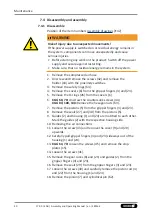
7.4 Disassembly and assembly
7.4.1 Disassemble
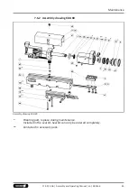
Position of the item numbers
WARNING
Risk of injury due to unexpected movements!
If the power supply is switched on or residual energy remains in
the system, components can move unexpectedly and cause
serious injuries.
•
Before starting any work on the product: Switch off the power
supply and secure against restarting.
•
Make sure, that no residual energy remains in the system.
1. Remove the compressed air hose.
2. Unscrew and remove the screws (42) and remove the
holder (10) with the proximity switches.
3. Remove the safety rings (64).
4. Remove the covers (6) from the gripper fingers (3) and (23).
5. Remove the O-rings (26) from the covers (6).
6.
KGG 60, 70:
Unscrew the countersunk screws (44).
KGG 80, 100, 140:
Remove the hexagon nuts (63).
7. Remove the pistons (5) from the gripper fingers (3) and (23).
8. Remove the seals (27) and (30) from the pistons (5).
9. Guides (2) and housing (1) and (24) are matched to each other.
Mark the guides (2) with the respective housing side.
10. Removing the air connections
11. Loosen the screw (43) and remove the cover (9) and (20)
upwards.
12. Carefully pull gripper fingers (3) and (23) sideways out of the
housing (1) and (24).
13.
KGG 60, 70:
Loosen the screws (45) and remove the stop
plates (15).
14. Loosen the screws (41).
15. Remove the gear racks (8) and (21) and guides (2) from the
gripper fingers (3) and (23).
16. Remove the seals (29) from the gripper fingers (3) and (23).
17. Loosen the screws (40) and carefully remove the piston rod (4)
and (22) from the housing (1) and (24).
18. Remove the pinion (7) and cylindrical pin (62).
Summary of Contents for KGG 100
Page 1: ...Translation of the original manual Assembly and Operating Manual KGG 2 Finger Parallel Gripper...
Page 49: ......
Page 50: ......
Page 51: ......

