Assembly
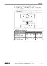
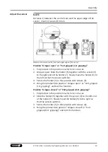
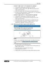
Position "Gripper open" or "Part gripped (I.D. gripping)"
1. Put product in the position in which it is to be set.
2. Slide the sensor 2 (2) from the right into the groove on the
holder until it switches.
3. Secure the sensor 2 (2) in this position using the set screw.
4. Bring the product into position "Gripper open" or "Part gripped
(I.D. gripping)" and test the function.
Position "Gripper closed" or "Part gripped (O.D. gripping)"
1. Put product in the position in which it is to be set.
2. Slide the sensor 1 (1) from the left into the groove on the
holder until it switches.
3. Secure the sensor 1 (1) in this position using the set screw.
4. Bring the product into position "Gripper closed" or "Part
gripped (O.D. gripping)" and test the function.
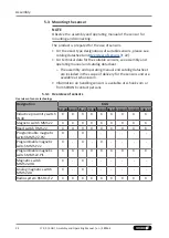
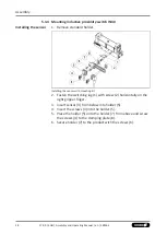
5.3.6 Mount programmable magnetic switch MMS 22-PI1
CAUTION
Risk of damage to the sensor during assembly!
•
Observe the maximal tightening torque.
NOTE
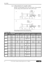
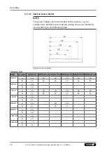
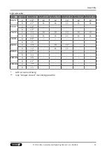
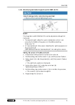
If there is no T-nut available, slide the sensor according to dimension
I1 into the groove (2),
Setting dimensions for magnetic switches
24].
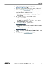
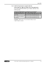
1. Turn the sensor (1) into the groove (2).
OR: Slide the sensor (1) into the groove (2) until the sensor (1)
stops at the T-nut (3).
2. Secure the sensor (1) using the set-screw (4).
Tightening torque: 10 Ncm
3. Adjust sensor (1), see sensor assembly and operating manual.
31
17.00 | KGG | Assembly and Operating Manual | en | 389166
Summary of Contents for KGG 100
Page 1: ...Translation of the original manual Assembly and Operating Manual KGG 2 Finger Parallel Gripper...
Page 49: ......
Page 50: ......
Page 51: ......

