background image

General

8

02.00 | GWB | Assembly and Operating Manual | en | 389122

1.4 Accessories

A wide range of accessories are available for this product
For information regarding which accessory articles can be used
with the corresponding product variants, see catalog data sheet.

1.4.1 Sensors

Overview of the compatible sensors

Designation

Type

Inductive proximity switches

IN

• Exact type designation of the compatible sensors see catalog.
• Information on handling sensors is available at schunk.com or

from SCHUNK contact persons.

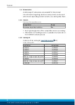
1.4.2 Sealing kit

Contents of the sealing kit, 

Assembly drawing

 [

}

 39].

ID.-No. of the seal kit

Seal kit for

ID number

GWB 34

0370615

GWB 44

0370616

GWB 54

0370617

GWB 64

0370618

GWB 64 - High-temperature (HT)

0370853

GWB 80

0370619

GWB 80 - High-temperature (HT)

0370817

GWB 100

0370723

Summary of Contents for GWB 100

Page 1: ...Translation of the original manual Assembly and Operating Manual GWB 2 finger angular gripper...

Page 2: ...tions for the purpose of technical improvement Document number 389122 Version 02 00 19 08 2019 en SCHUNK GmbH Co KG All rights reserved Dear Customer thank you for trusting our products and our family...

Page 3: ...are parts 9 2 5 Gripper fingers 10 2 6 Ambient conditions and operating conditions 10 2 7 Personnel qualification 11 2 8 Personal protective equipment 12 2 9 Notes on safe operation 12 2 10 Transport...

Page 4: ...or closes abruptly 31 5 3 Gripping force is dropping 31 5 4 Opening angle not correct 32 5 5 Gripper opens or closes too slowly 32 6 Maintenance 33 6 1 Notes 33 6 2 Maintenance and lubrication interv...

Page 5: ...manual Illustrations in this manual are provided for basic understanding and may differ from the actual product design In addition to these instructions the documents listed under Applicable documents...

Page 6: ...0 GWB 100 1 1 4 Variants This operating manual applies to the following variations GWBwithout gripping force maintenance GWBwith gripping force maintenance O D gripping AS GWBwith gripping force maint...

Page 7: ...sory pack 1 3 1 Accessory pack Content of the accessories pack Assembly drawing 39 ID No of the accessory pack Accessory pack for ID number GWB 34 5509422 GWB 34 High temperature HT 395509422 GWB 44 5...

Page 8: ...compatible sensors Designation Type Inductive proximity switches IN Exact type designation of the compatible sensors see catalog Information on handling sensors is available at schunk com or from SCHU...

Page 9: ...r industrial and industry oriented use Appropriate use of the product includes compliance with all instructions in this manual 2 2 Not intended use It is not intended use if the product is used for ex...

Page 10: ...ze for the application 2 6 Ambient conditions and operating conditions Required ambient conditions and operating conditions Incorrect ambient and operating conditions can make the product unsafe leadi...

Page 11: ...lated to the product Trained electrician Due to their technical training knowledge and experience trained electricians are able to work on electrical systems recognize and avoid possible dangers and k...

Page 12: ...les when handling hazardous substances Wear close fitting protective clothing and also wear long hair in a hairnet when dealing with moving components 2 9 Notes on safe operation Incorrect handling of...

Page 13: ...ntil the malfunction has been rectified Test the product after a malfunction to establish whether it still functions properly and no increased risks have arisen 2 12 Disposal Handling of disposal The...

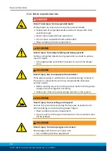
Page 14: ...ention rules Use suitable assembly and transport equipment and take precautions to prevent jamming and crushing Incorrect lifting of loads Falling loads may cause serious injuries and even death Stand...

Page 15: ...through technical safety measures The protective cover and protective fence must be rigid enough to withstand the maximum possible movement energy EMERGENCY STOP switches must be easily and quickly ac...

Page 16: ...measures to secure the danger zone WARNING Risk of injury due to unexpected movements If the power supply is switched on or residual energy remains in the system components can move unexpectedly and...

Page 17: ...nexpectedly and cause serious injuries Disassemble the product cautiously Make sure that no residual energy remains in the system WARNING Risk of injury from objects falling during energy supply failu...

Page 18: ...er double stroke cm3 4 5 16 0 36 0 57 0 110 0 217 0 Nominal working pressure bar 6 0 Min pressure bar 4 0 Max pressure bar 6 5 Closing time s 0 3 0 4 0 6 0 6 0 7 0 55 Opening time s 0 4 0 5 0 7 0 7 0...

Page 19: ...02 00 GWB Assembly and Operating Manual en 389122 19 3 1 GWB 100 gripping force diagram GWB 100 gripping force diagram 3 2 Max permissible forces and moments on the claw jaws max finger length of the...

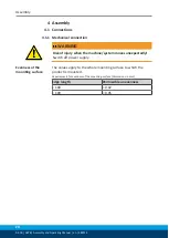
Page 20: ...RNING Risk of injury when the machine system moves unexpectedly Switch off power supply Evenness of the mounting surface The values apply to the whole mounting surface to which the product is mounted...

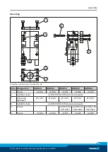
Page 21: ...Designation GWB34 GWB44 GWB54 GWB64 GWB80 1 Screw 4x M4 4x M4 4x M5 4x M6 4x M6 2 Cylindrical pin 2 x DIN EN ISO 8734 accessory pack 3 Centering diameter 10H7 20H7 20H7 25H7 30H7 4 Cylindrical pin 2 x...

Page 22: ...6 x 20 2 M5 for hose connection 3 4x DIN EN ISO 4762 M8 x 65 4 4x M10 screw 15 mm depth of engagement 5 2x DIN EN ISO 8734 8m6 x 20 6 4x M10 screw 15 mm depth of engagement NOTE When mounting the modu...

Page 23: ...ecure position However the use of a SDV P pressure maintenance valve is recommended in this case in order to maintain the dynamic effect for some time Product variants are also offered with mechanical...

Page 24: ...Gripper open Gripper closed Double check valve Pneumatic connection GWB 100 Open only the air connections that are needed Close unused main air connections using the screw plugs from the enclosed pack...

Page 25: ...stmenrt screw with the lock nut after making the setting To do so remove the stop bar and bring the gripper into the open 90 position GWB 100 Adjustment range 0 180 Use a size 6 hexagon socket wrench...

Page 26: ...d Overview of sensors 26 For technical data for the suitable sensors see assembly and operating manual and catalog datasheet The assembly and operating manual and catalog datasheet are included in the...

Page 27: ...r 1 1 into the bracket 3 until it touches the control cam 4 Pull sensor 1 1 back by approx 0 5 mm Fix sensor 1 1 using the attachment screws 2 Max tightening torque 10 Ncm Connect sensor 1 1 Open and...

Page 28: ...y approx 0 5 mm Tighten screw 4 Tightening torque 20 Ncm Connect sensor 1 1 Bring the product into position Gripper open to test for proper functioning Position Gripper closed Move the product to the...

Page 29: ...ngers optionally from the inside or outside Example of how to design a top jaw A Centering for gripper finger B Groove for cylindrical pin F Thread for cylindrical screw Table of dimensions Type A B C...

Page 30: ...30 02 00 GWB Assembly and Operating Manual en 389122 Type Max finger length Nominal gripping force L in mm Lo in mm Po in mm GWB 34 40 21 64 GWB 44 50 31 180 GWB 54 60 33 290 GWB 64 80 40 450 GWB 80 1...

Page 31: ...osed Open the flow control valve Component part defective Replace component or send it to SCHUNK for repair The aperture angle is limited to 0 Check opening angle limitation 5 2 Module opens or closes...

Page 32: ...aperture angle is limited to 0 Check opening angle limitation Pressure drops below minimum Check air supply Pneumatic connection 23 5 5 Gripper opens or closes too slowly Possible cause Corrective act...

Page 33: ...at temperatures above 60 C leading to possible product damage Reduce the lubricant intervals accordingly Maintenance and lubrication interval Size GWB 34 100 Interval Mio cycles 2 6 3 Lubricants Lubr...

Page 34: ...an move unexpectedly and cause serious injuries Before starting any work on the product Switch off the power supply and secure against restarting Make sure that no residual energy remains in the syste...

Page 35: ...e guide bushing 4 Unscrew the set screws 20 from the gripper fingers 3 To do so insert an Allen key through the assembly bores in the cover housing 2 The gripper fingers must be in closed position for...

Page 36: ...the system components can move unexpectedly and cause serious injuries Before starting any work on the product Switch off the power supply and secure against restarting Make sure that no residual ene...

Page 37: ...5 with suitable pliers for safety rings Remove the cover 2 WARNING The parts are under spring tension F 500 N Carefully loosen the screw 28 35 mm Clamp the gripper between the cylinder piston 6 and to...

Page 38: ...ation points basic lubrication 33 Oil or grease bare external steel parts Replace all wear parts seals Position of the wearing parts Assembly drawing 39 Seal kit Sealing kit 8 Assembly Assembly takes...

Page 39: ...GWB 100 18 2 7 5 8 5 8 12 21 6 6 Assembly drawing The following figures are example images They serve for illustration and assignment of the spare parts Variations are possible depending on size and...

Page 40: ...enance 40 02 00 GWB Assembly and Operating Manual en 389122 6 6 2 GWB 100 assembly GWB 100 assembly Wearing part replace during maintenance Included in the seal kit Seal kit can only be ordered comple...

Page 41: ...finger angular gripper GWB pneumatic ID number 0307125 0307140 The partly completed machine may not be put into operation until conformity of the machine into which the partly completed machine is to...

Page 42: ...ents 1 1 1 Definitions X 1 1 2 Principles of safety integration X 1 1 3 Materials and products X 1 1 4 Lighting X 1 1 5 Design of machinery to facilitate its handling X 1 1 6 Ergonomics X 1 1 7 Operat...

Page 43: ...2 2 Interlocking movable guards X 1 4 2 3 Adjustable guards restricting access X 1 4 3 Special requirements for protective devices X 1 5 Risks due to other hazards 1 5 1 Electricity supply X 1 5 2 Sta...

Page 44: ...irements for certain categories of machinery X 2 1 Foodstuffs machinery and machinery for cosmetics or pharmaceutical products X 2 2 Portable hand held and or guided machinery X 2 2 1 Portable fixing...

Reviews: