Assembly
02.00 | EMH | Assembly and Operating Manual | en | 1393220
21
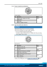
5.3.1 Power connection pin allocation
Power connection
Pin
Function
Type
1
Logic power supply (+24 VDC)
Input
2
GND power
3
GND logic
4
Power supply (+24 VDC)
5.3.2 Logic connection pin allocation
CAUTION
Material damage due to incorrect grounding!
Permanent damage to the electronics possible!
•
Ensure reliable equipotential bonding.
To do this, always connect the pin 3 (GND) with the grounding
of the higher-level control.
Logic connection
Pin
Function
Type
1
Magnetization ON
Input
2
Magnetization OFF
3
Ground
GND
4
Message "Workpiece available"
Output
5
Message "Malfunction"
6
Message "Magnetization status"
7
Force signal A *
Input
8
Force signal B *
* Defines the holding force level,


