


Assembly and settings
34
05.00 | EGS | Assembly and Operating Manual | en | 389746
5.2.2 Electrical connection
CAUTION
Material damage due to incorrect assembly!
•
When connecting the cable, do not exceed the maximum
tightening torque of 0.8 Nm for the cable.
•
Make sure that the connections are not stressed due to
pulling or pressure forces or due to vibrations. Apply the
corresponding strain relief devices if required.
NOTE
When using customer-supplied cable: at least 4 x 0.25 mm²
The gripper and the swivel axes are controlled separately. In order
to use both axes, both connectors for voltage supply and control
must be connected.
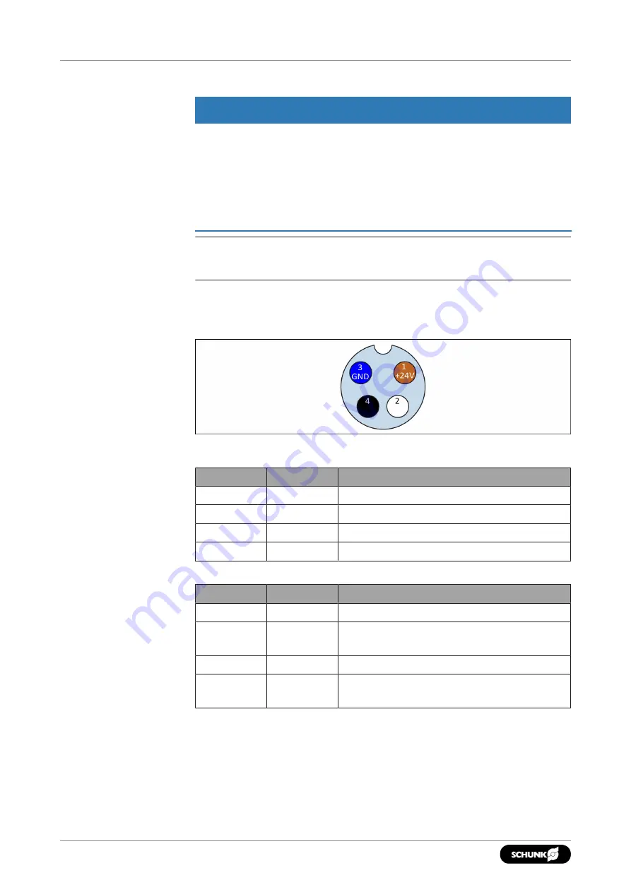
Voltage supply and
control
M8 connection plug for gripper and swivel axis (view of plug)
Connection assignment gripper
PIN
Wire strand Signal
1
Brown
+ 24 V
2
White
Opens gripper
3
Blue
GND
4
Black
Closes gripper
Connection assignment swivel axis
PIN
Wire strand Signal
1
Brown
+ 24 V
2
White
Pivot swiveling axis counter clockwise
(GUZS),
3
Blue
GND
4
Black
Pivot swiveling axis clockwise
(UZS),


