background image

Assembly and settings

03.00 | EGI | Assembly and Operating Manual | en | 1396645

37

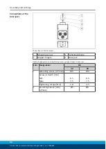
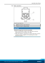
5.3.2 Cable connections

Cable outlets (example EGI 80)

1

Cable connector communication

2

Cable connector voltage supply

CAUTION

Material damage due to incorrect assembly!

When connecting the cable, do not exceed the maximum
tightening torque of 0.8 Nm for the cable.

Make sure that the connections are not stressed due to tensile
or pressure forces. Apply the corresponding strain relief
devices if required.

Summary of Contents for EGI 40

Page 1: ...Translation of Original Operating Manual Assembly and Operating Manual EGI Gripper for small components...

Page 2: ...for the purpose of technical improvement Document number 1396645 Version 03 00 07 07 2020 en SCHUNK GmbH Co KG All rights reserved Dear Customer thank you for trusting our products and our family own...

Page 3: ...ient conditions and operating conditions 9 2 6 1 Environmental conditions 10 2 6 2 Insulation resistance and voltage resistance in accordance with EN 60204 1 11 2 7 Personnel qualification 12 2 8 Pers...

Page 4: ...anical connection 33 5 3 Electrical connection 35 5 3 1 Pin allocation 35 5 3 2 Cable connections 37 5 3 3 Wiring diagram 38 5 3 4 External protection 38 5 3 5 Connecting ground cable 39 5 4 Combining...

Page 5: ...or basic understanding and may differ from the actual product design In addition to these instructions the documents listed under Applicable documents 6 are applicable 1 1 1 Presentation of Warning La...

Page 6: ...result Final result 1 1 5 Applicable documents General terms of business Catalog data sheet of the purchased product Assembly and operating manuals of the accessories Software manual EGI with PROFINE...

Page 7: ...pe of delivery includes Gripper for small components EGI in the version ordered firmware Assembly and Operating Manual DVD EGI 40 4x centering sleeve 5x4 35 2x centering sleeve 8x5 35 EGI 80 4x center...

Page 8: ...rs from the appropriate use is regarded as misuse This includes in particular Use outside of load limits Use by unauthorized personnel Use in unintended environments Use with gripping parameters e g g...

Page 9: ...it to malfunction Use only original spare parts or spares authorized by SCHUNK 2 5 Gripper fingers Requirements of gripper fingers Only replace gripper fingers if no residual energy can be released Ma...

Page 10: ...subjected to a vibration and shock inspection during transport and in operation with respect to the ambient influences and withstands the required loads The product may only be used in the following...

Page 11: ...sing ground in order to protect against overvoltage For measurements of the insulation resistance in accordance with EN 60204 1 no voltage levels above the permitted operating voltage range may be use...

Page 12: ...lated to the product Trained electrician Due to their technical training knowledge and experience trained electricians are able to work on electrical systems recognize and avoid possible dangers and k...

Page 13: ...les when handling hazardous substances Wear close fitting protective clothing and also wear long hair in a hairnet when dealing with moving components 2 9 Notes on safe operation Incorrect handling of...

Page 14: ...or in case of malfunctions Immediately remove the product from operation and report the malfunction to the responsible departments persons Order appropriately trained personnel to rectify the malfunct...

Page 15: ...e product s safety and cause serious injuries and considerable material damage Have all work carried out by appropriately qualified personnel For all work secure the product against accidental operati...

Page 16: ...fective it must be assumed that the drive movement is faulty with its action being dependent on the control unit and the current operating condition of the drive Perform maintenance work modifications...

Page 17: ...d to all electrical components according to the wiring diagram Check whether covers and protective devices are fitted to prevent contact with live components Do not touch the product s terminals when...

Page 18: ...ctric components of the drive system and their feed lines If the use of such devices is necessary When starting up the electric drive and control system check the machine or automated system for possi...

Page 19: ...s Surfaces of components can heat up severely during operation Skin contact with hot surfaces causes severe burns to the skin For all work in the vicinity of hot surfaces wear safety gloves Before car...

Page 20: ...Ambient temperature C Min Max 5 55 Electrical operating data Nominal voltage VDC 24 10 Max current input logic A 0 25 Max current input power A 0 7 1 5 Communication interface PROFINET 100 MBit s IRT...

Page 21: ...specific workpiece depends on the design of the gripper finger EGI 40 Gripping force diagram EGI 40 F N Gripping force L mm Finger length EGI 80 Gripping force diagram EGI 80 F N Gripping force L mm F...

Page 22: ...determine the nominal gripping force the product is installed with a positive locking on an aluminum plate 200x200x20 mm The product can hold this nominal gripping force up to an ambient temperature...

Page 23: ...ce EGI 80 has a system for gripping force maintenance EGI 40 has no gripping force maintenance The product is controlled via one of the following interfaces PROFINET EtherCAT or EtherNet IP In prepara...

Page 24: ...tion control With gripping force maintenance When the requested position is reached the gripping force maintenance is activated and the motor is switched off Without gripping force maintenance When th...

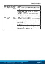
Page 25: ...ation inactive LED flashes quickly Connection active communication active NS Network status Red Green LED off No connection to the control system available LED lights up green Connection to the contro...

Page 26: ...No supply voltage power present or supply voltage power is outside the operating range for the module LED lights up green Supply voltage power is present L A2 Link Activity 2 Network connection and ne...

Page 27: ...hed a connection LED lights up red Duplicate network address present Serious network error present LED flashes red Timeout for one or more connections MS Module status Red Green LED off No supply volt...

Page 28: ...ply voltage power present or supply voltage power is outside the operating range for the module LED lights up green Supply voltage power is present L A OUT Link Activity 2 Network connection and netwo...

Page 29: ...erious error The bus interface has been put into a physically passive state Contact SCHUNK Service ERROR ERR LED Red LED off No supply voltage present and or no error LED flashes red Invalid configura...

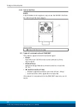
Page 30: ...cover plug 4 5 Types of communication of PROFINET The product supports the communication types TCP IP Open Ethernet TCP IP communication without real time requirements RT Real Time IO data exchange be...

Page 31: ...dustrial Protocol CIP defined by the Open DeviceNet Vendor Association ODVA Two EtherNet IP ports Topology linear 10 100 Mbit full half duplex Ethernet Address Conflict Detection ACD 4 7 Communication...

Page 32: ...ication Avoid exposure to additional heat e g caused by attachments or by the attached axles Overview Check the evenness of the mounting surface Mechanical connection 33 Choose the installation positi...

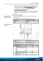
Page 33: ...ief devices if required 5 2 Mechanical connection Evenness of the mounting surface The values apply to the whole mounting surface to which the product is mounted Requirements for evenness of the mount...

Page 34: ...s to the base jaws 1 Mounting screw 3 Centering sleeve 2 Gripper fingers 4 Base jaw Depth of engagement and tightening torque gripper finger to base jaw Item Designation EGI 40 80 1 Mounting screw 2 P...

Page 35: ...and logic Observe the PIN assignment of the connecting terminals Make sure that all components are grounded correctly NOTE Note on EMC conformity in accordance with EN 61000 6 4 2007 A1 2011 The produ...

Page 36: ...Logic 2 GND Logic 3 GND Power 4 24 V Power Communication EGI 40 The communication interface PROFINET EtherCAT or EtherNet IP is implemented via two D coded M8 sockets EGI 80 The communication interfa...

Page 37: ...nnector communication 2 Cable connector voltage supply CAUTION Material damage due to incorrect assembly When connecting the cable do not exceed the maximum tightening torque of 0 8 Nm for the cable M...

Page 38: ...c voltage PWR voltage supply Shield via connector thread Shield via connector thread PROFINET Ethernet IP P2 EtherCAT OUT PROFINET EtherNet IP P1 EtherCAT IN Wiring diagram EGI 5 3 4 External protecti...

Page 39: ...must be established between the product and the machine on the customer s premises The ground cable must be mounted on the threaded hole identified by the ground marking NOTE Only connect the ground...

Page 40: ...the communication connection Combining multiple products 1 PROFINET EtherCAT or EtherNet IP Socket P1 2 Bus cable 3 PROFINET EtherCAT or EtherNet IP Socket P2 When several products are combined commu...

Page 41: ...referencing jog mode positioning gripping Configuring limit stroke transfer work settings reboot Service functions display and save general product information and errors download the GSDML file Start...

Page 42: ...as identification and status information Any possible errors will be shown in the lower area of the status information that can be opened out 4 If applicable rectify the error and acknowledge the erro...

Page 43: ...green Switch on the power voltage LED PWR lights up green Make sure that the product is ready to operate and not reporting any errors LED MS lights up green product status LED NS lights up green netwo...

Page 44: ...nowledged and the product is driven by the superordinate control system Behavior on canceling the connection between the superordinate control system and the product On canceling the connection the pr...

Page 45: ...ntrol or in motion 7 2 Product moves in a jerky fashion is sluggish or blocked Possible cause Corrective action Product is overloaded Check load situation e g maximum permissible finger weight maximum...

Page 46: ...connected emergency stop chain interrupted safety light curtain triggered Check the power supply requirement Technical data 20 Insufficient voltage Error message present Eliminate fault and acknowled...

Page 47: ...with compressed air Inspect the product for damage Replace the product if necessary Have all repair work on the product carried out only by SCHUNK Update firmware 8 2 Disassembly and assembling This...

Page 48: ...ollowing directive at the time of declaration The declaration is rendered invalid if modifications are made to the product EMC Directive 2014 30 EU Directive of the European Parliament and the Council...

Page 49: ...r small components EGI electric ID number 1328833 1328834 1328836 1328837 1328835 1328838 The partly completed machine may not be put into operation until conformity of the machine into which the part...

Page 50: ...Essential Requirements 1 1 1 Definitions X 1 1 2 Principles of safety integration X 1 1 3 Materials and products X 1 1 4 Lighting X 1 1 5 Design of machinery to facilitate its handling X 1 1 6 Ergono...

Page 51: ...2 2 Interlocking movable guards X 1 4 2 3 Adjustable guards restricting access X 1 4 3 Special requirements for protective devices X 1 5 Risks due to other hazards 1 5 1 Electricity supply X 1 5 2 Sta...

Page 52: ...rements for certain categories of machinery X 2 1 Foodstuffs machinery and machinery for cosmetics or pharmaceutical products X 2 2 Portable hand held and or guided machinery X 2 2 1 Portable fixing a...

Reviews: