background image

Maintenance

8.3 Disassembly and assembly

Disassembling

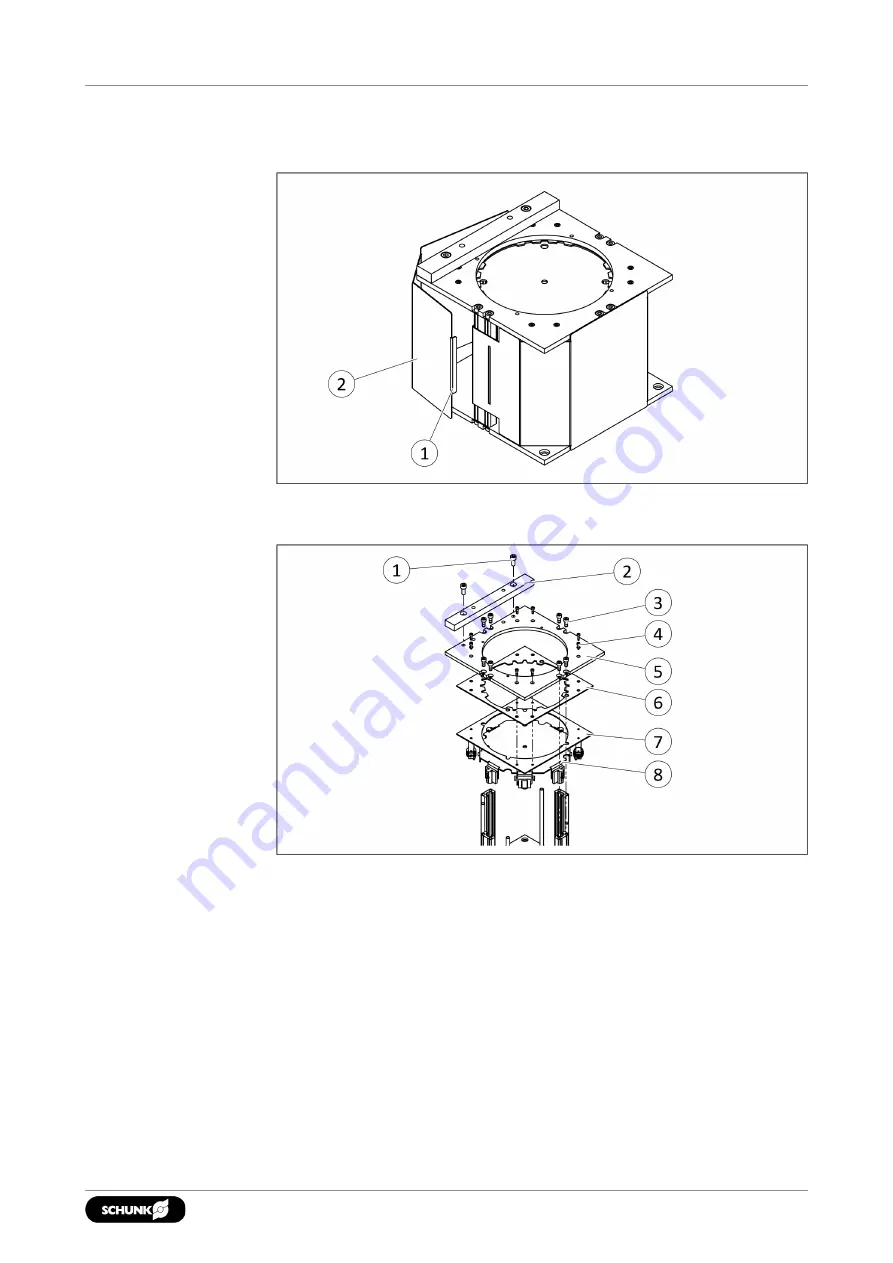
Remove debris shield

1. Lift tabs (1) and remove debris shield (2).

Disassemble the media feeder

2. Remove the sanding discs from the media feeder.
3. Loosen the fastening screws (1) and disassemble the alignment

rail (2).

4. Loosen the fastening screws (3) and remove the upper

plate (5) and feed tray assembly (8) from the media feeder.

5. Loosen the fastening screws (4) and remove the feed tray

assembly (8) from the upper plate (5).

6. Check retaining gasket (6) for damage and replace if necessary.

Align the through hole on the retaining gasket (6) with the
through hole on the support bracket (7)

33

01.00 | AOV-MC | Assembly and Operating Manual | en | 1461420

Summary of Contents for AOV-MC

Page 1: ...Translation of Original Operating Manual Assembly and Operating Manual AOV MC Media changer for orbital sander...

Page 2: ...ion 01 00 01 02 2021 en Dear Customer thank you for trusting our products and our family owned company the leading technology supplier of robots and production machines Our team is always available to...

Page 3: ...9 2 9 Malfunctions 9 2 10 Disposal 10 2 11 Fundamental dangers 10 2 11 1 Protection during handling and assembly 10 2 11 2 Protection during commissioning and operation 11 2 11 3 Protection against d...

Page 4: ...8 Maintenance 32 8 1 Notes 32 8 2 Maintenance interval 32 8 3 Disassembly and assembly 33 8 4 Replace the Velcro disc on the media checker 35 8 5 Replace needles 36 8 6 Assembly drawings 37 9 EU Decla...

Page 5: ...asic understanding and may differ from the actual product design In addition to these instructions the documents listed under Applicable documents 6 are applicable 1 1 1 Presentation of Warning Labels...

Page 6: ...age schunk com 1 1 4 Components This manual applies to the following components Media feeder AOV MF Media checker AOV MCH Media remover AOV MRA 1 2 Warranty If the product is used as intended the warr...

Page 7: ...oriented use Appropriate use of the product includes compliance with all instructions in this manual 2 2 Not intended use It is not intended use if the product is used for example as a pressing tool s...

Page 8: ...the complete assembly and operating manual Observe the national safety regulations and rules and general safety instructions The following personal qualifications are necessary for the various activit...

Page 9: ...ar long hair in a hairnet when dealing with moving components Wear ear protection and safety goggles during the machining process 2 8 Transport Handling during transport Incorrect handling during tran...

Page 10: ...energy in the system Do not move parts by hand while the energy supply is connected Do not reach into the movement area of the product during operation 2 11 1 Protection during handling and assembly I...

Page 11: ...ive it must be assumed that the drive movement is faulty with its action being dependent on the control unit and the current operating condition of the drive Perform maintenance work modifications and...

Page 12: ...ead to serious injury or death Take appropriate protective measures to secure the danger zone WARNING Risk of injury due to unexpected movements If the power supply is switched on or residual energy r...

Page 13: ...ical data 3 Technical data Designation AOV MC Nominal operating pressure bar 4 1 6 2 Pressure medium Compressed air clean dry filtered 5 m oil free 13 01 00 AOV MC Assembly and Operating Manual en 146...

Page 14: ...and description 4 1 Design Media feeder 1 Alignment rail 2 Media retaining gasket 3 Media storage 4 Through holes for mounting Media remover 1 Needle gripper 2 Plate with Through holes for mounting 3...

Page 15: ...gh holes for mounting 2 Media detection piston 3 Sensor connection 4 2 Description Automatic sanding disc changer for mounting and removing sanding discs and checking the change procedure 15 01 00 AOV...

Page 16: ...oid contact Wear suitable protective equipment 1 Mount the components of the product Mechanical connection 17 2 Load the media feeder in small stacks with 15 25 sanding discs The media must be inserte...

Page 17: ...he mounting surface Dimensions in mm Edge length Permissible unevenness 100 0 02 100 0 05 The media checker and the media feeder can be mounted in all orientations The media remover must be mounted in...

Page 18: ...ction NOTE Observe the requirements for the compressed air supply Technical data 13 Use a 5 2 directional control valve to control the two air connections 1 Retract needle air connection 2 Extend need...

Page 19: ...n Proximity switch on the media checker Type of switching PNP Switching function Closer Connector M8 Pin Wire strand Designation 1 Brown 10 to 30 VDC 3 Blue GND 4 Black Output 19 01 00 AOV MC Assembly...

Page 20: ...a sanding process of 15 seconds or more can cause the Velcro to bind more strongly than a manually applied sanding disc 6 2 Pick up sanding discs Load media feeder In doing so observe the following Re...

Page 21: ...the backer pad is pressed carefully against the alignment rail Slight resistance can be felt when moving the backer pad manually Backer pad is pressed against alignment rail 3 Move the sander linearly...

Page 22: ...pad along the alignment rail over the opening 4 Align the sander exactly over the opening Align the backer pad exactly over the opening 5 Check whether the orbit pattern has been deflected accordingly...

Page 23: ...l 7 During this movement reduce the inclination until the sander is parallel to the media stack The stack of sanding discs is pressed down 8 Short pause approx 500 ms Stack with sanding discs is press...

Page 24: ...nual en 1461420 Lift the sander 10 Recommended Repeat steps 4 through 9 once to ensure a sanding disc has been picked up 11 Move the sander to the starting position HOME The pickup process is complete...

Page 25: ...dia checker A View from the side B View from above 2 Move the sander in the direction of the media checker until the backer pad makes contact with the Velcro fastener Backer pad and media checker are...

Page 26: ...1 00 AOV MC Assembly and Operating Manual en 1461420 Move the backer pad away from the media checker 4 Wait briefly so that the media checker can process the signal 5 Move the sander to the starting p...

Page 27: ...ing the sander should be set to 0 7 bar The sander is in the starting position HOME 1 Move the sander over the media remover The contact tester backer pad side which was in contact with the media chec...

Page 28: ...en 1461420 Backer pad on media remover 3 Extend needles 4 Wait briefly Then lift the sander a few millimeters The needles are hooked onto the backer pad The orbit height of the sander can change depen...

Page 29: ...diameter so that the sanding disc is completely removed during regular operation The angle at which the sander is moved away from the media remover varies depending on the sanding disc and the design...

Page 30: ...k in the media feeder is excessively curved Stack the sanding discs in the feeder in an offset pattern Remove the stack and carefully bend and straighten by hand 7 2 The sander removes more than one s...

Page 31: ...pressed air lines switched Check air supply Pneumatic connection 18 Compressed air lines are not installed optimally Pressure drops below minimum Observe the requirements for the compressed air supply...

Page 32: ...ear replace if necessary Replace the Velcro disc on the media checker 35 Check the needles on the media remover for damage and wear replace if necessary Replace needles 36 monthly Check retaining gask...

Page 33: ...ble the alignment rail 2 4 Loosen the fastening screws 3 and remove the upper plate 5 and feed tray assembly 8 from the media feeder 5 Loosen the fastening screws 4 and remove the feed tray assembly 8...

Page 34: ...e and the feed tray assembly This makes it easier to insert the feed tray assembly during assembly Replace glide Replace springs 1 Check springs 2 on feed tray assembly 3 for damage 2 If damaged Hold...

Page 35: ...he fastening screw 3 5 9 Nm Max tightening torque of the fastening screw 1 10 1 Nm 8 4 Replace the Velcro disc on the media checker 1 Loosen screw 1 with 2 mm hexagon socket wrench 2 Remove damaged or...

Page 36: ...t Positions of the item numbers on the graphic AOV MRA media remover Assembly drawings 37 1 Remove the compressed air hose 2 Disassemble the media remover from the application 3 Loosen the fastening s...

Page 37: ...Maintenance 8 6 Assembly drawings Media feeder AOV MF5 37 01 00 AOV MC Assembly and Operating Manual en 1461420...

Page 38: ...Maintenance 38 01 00 AOV MC Assembly and Operating Manual en 1461420 Media feeder AOV MF6...

Page 39: ...Maintenance Media checker AOV MCH Media remover AOV MRA 39 01 00 AOV MC Assembly and Operating Manual en 1461420...

Page 40: ...monized standards especially EN 61326 2 3 2013 Electrical equipment for measurement control and laboratory use EMC requirements Part 2 3 Particular requirements Test configuration operational conditio...

Page 41: ...valid if modifications are made to the product Product designation Washer rack AOV MF5 MF6 ID number 1460781 1460783 2001 95 EC General product safety Applied harmonized standards especially EN ISO 12...

Page 42: ...Washer remover AOV MRA ID number 1460797 The partly completed machine may not be put into operation until conformity of the machine into which the partly completed machine is to be installed with the...

Page 43: ...ign of machinery to facilitate its handling X 1 1 6 Ergonomics X 1 1 7 Operating positions X 1 1 8 Seating X 1 2 Control Systems 1 2 1 Safety and reliability of control systems X 1 2 2 Control devices...

Page 44: ...e guards restricting access X 1 4 3 Special requirements for protective devices X 1 5 Risks due to other hazards 1 5 1 Electricity supply X 1 5 2 Static electricity X 1 5 3 Energy supply other than el...

Page 45: ...stuffs machinery and machinery for cosmetics or pharmaceutical products X 2 2 Portable hand held and or guided machinery X 2 2 1 Portable fixing and other impact machinery X 2 3 Machinery for working...

Page 46: ......

Page 47: ......

Page 48: ...G Clamping and gripping technology Bahnhofstr 106 134 D 74348 Lauffen Neckar Tel 49 7133 103 0 Fax 49 7133 103 2399 info de schunk com schunk com Folgen Sie uns I Follow us 02 2021 2021 SCHUNK GmbH Co...

Reviews: