3
TFH 232 AS
Operating instructions
Safety foot switches
EN
AS-i Outputs:
DO 0 DO 3:
no Function
AS-i Parameter bits:
P0:
Channel 2 switched;
P1 P3:
no function
Input module address:
0, preset to address 0, can be changed
through AS-interface bus master
or hand-held programming device
LED switching conditions display (internal):
LED yellow:
Channel 1, SaW-Bit 01
LED green-red (AS-i Duo LED):
AS-Interface supply voltage /
AS-Interface communication error /
slave address = 0 or
periphery error detected
LED yellow:
Channel 2, SaW-Bit 23
Only for use in Pollution Degree 2 Environment
For use in NFPA 79 Applications only
Adapters providing ield wiring means are available from
the manufacturer Refer to manufacturer’s information
2.5 Safety classification
Standards:
EN ISO 13849-1, IEC 61508
PL:
up to c
Control category:
up to 1
PFH-value:
≤ 1,14 × 10
-6
/h
up to max 36500 switching cycles/year
PFH-value:
≤ 2,94 × 10
-6
/h
up to max 36500 switching cycles/year
SIL:
up to 1
Service life:
20 years
3. Mounting
3.1 General mounting instructions
The itting may only be carried out by authorised personnel
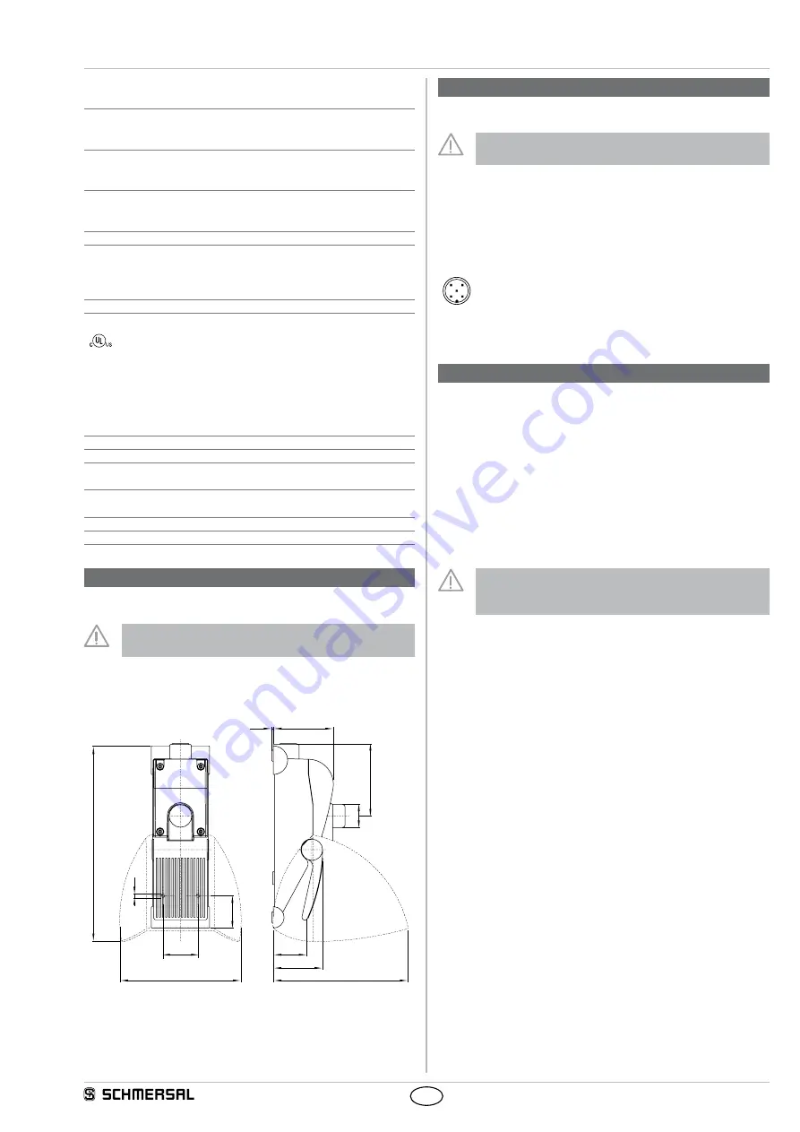
3.2 Dimensions
All measurements in mm
274
84
2,2
189
48
69
170
M6
45
49
100
¤33
4. Electrical connection
4.1 General information for electrical connection
The electrical connection may only be carried out by
authorised personnel in a de-energised condition
The connection to the AS-Interface system is realised through an M12
connector The connector is A- coded, the wiring configuration is deter-
mined as follows (to EN 50295)
Pin assignment M12 connector
5-pole
3
2
5
1
4
PIN 1: AS-i +
PIN 2: spare
PIN 3: AS-i -
PIN 4: spare
PIN 5: FE (functional earth connection)
5. Functions and configuration
5.1 Programming the slave address
The slave address is programmed through the AS-i connector Any
address from 1 to 31 can be set by means of the AS-i bus master or a
hand-held programming device
5.2 Configuration of the safety monitor
The safety switch can be configured in the ASIMON
configuration software with the following monitoring devices
(refer to ASIMON manual):
Double channel independent
• Optionally with startup test
The configuration of the safety monitor must be tested and
confirmed by a qualified and authorised safety expert/safety
engineer
5.3 Status signal "safety release"
The "safety release" status signal from a Safety at Work slave can be
cyclically queried by the control system through the AS-i master To that
effect, the 4 input bits with the varying SaW code of a Safety at Work
slave are evaluated through an OR operation with 4 inputs in the control
system


