


5
SRB301HC/T-24V
SRB301HC/T-230V
Operating instructions
Safety-monitoring module
EN
8.2 Start configuration
External reset button (non-monitored start) (see Fig. 3)
• The reset button is integrated in the feedback circuit in series as shown.
• The safety-monitoring module is activated upon actuation of the reset
button.
Automatic start (Fig. 4)
• The automatic start is programmed by connecting the feedback circuit
to the terminals. If the feedback circuit is not required, establish a
bridge.
• Caution: Not admitted without additional measure due to the risk of
gaining access by stepping behind!
• Within the meaning of EN 60204-1 paragraph 9.2.5.4.2, the operating
mode "automatic start" is only restrictedly admissible. In particular, any
inadvertent restart of the machine must be prevented by other suitable
measures.
X2
J
S
K
B
K
A
X1
X2
X1
K
B
K
A
S
Fig. 3
Fig. 4
8.3 Sensor configuration
Dual-channel emergency stop circuit with command devices to
DIN EN ISO 13850 (EN 418) and EN 60947-5-5 (Fig. 5)
• Wire breakage and earth leakage in the control circuits are detected.
• Cross-wire shorts between the control circuits are detected.
• Category 4 – PL e to DIN EN ISO 13849-1 possible.
Dual-channel guard door monitoring circuit with interlocking
device to EN 1088 (see Fig. 6)
• With at least one positive-break position switch
• Wire breakage and earth leakage in the control circuits are detected.
• Cross-wire shorts between the control circuits are detected.
• Category 4 – PL e to DIN EN ISO 13849-1 possible.
Safety mat to DIN EN 1760-1 (see Fig. 7)
• In combination with SMS safety mat (from Schmersal)
Category 3 – PL "e" to DIN EN ISO 13849-1
• Without reset function
• The connection of the inputs is realised through the safety mat here.
• When the safety mat is actuated, the potentials of both inputs are con
-
nected, so that a cross-wire short is created and the device is safely
shut down.
• Category 3 – PL e to DIN EN ISO 13849-1 possible.
S14
S13
S23
S24
S14
S13
S23
S24
S14
S13
S23
S24
Fig. 5
Fig. 6
Fig. 7
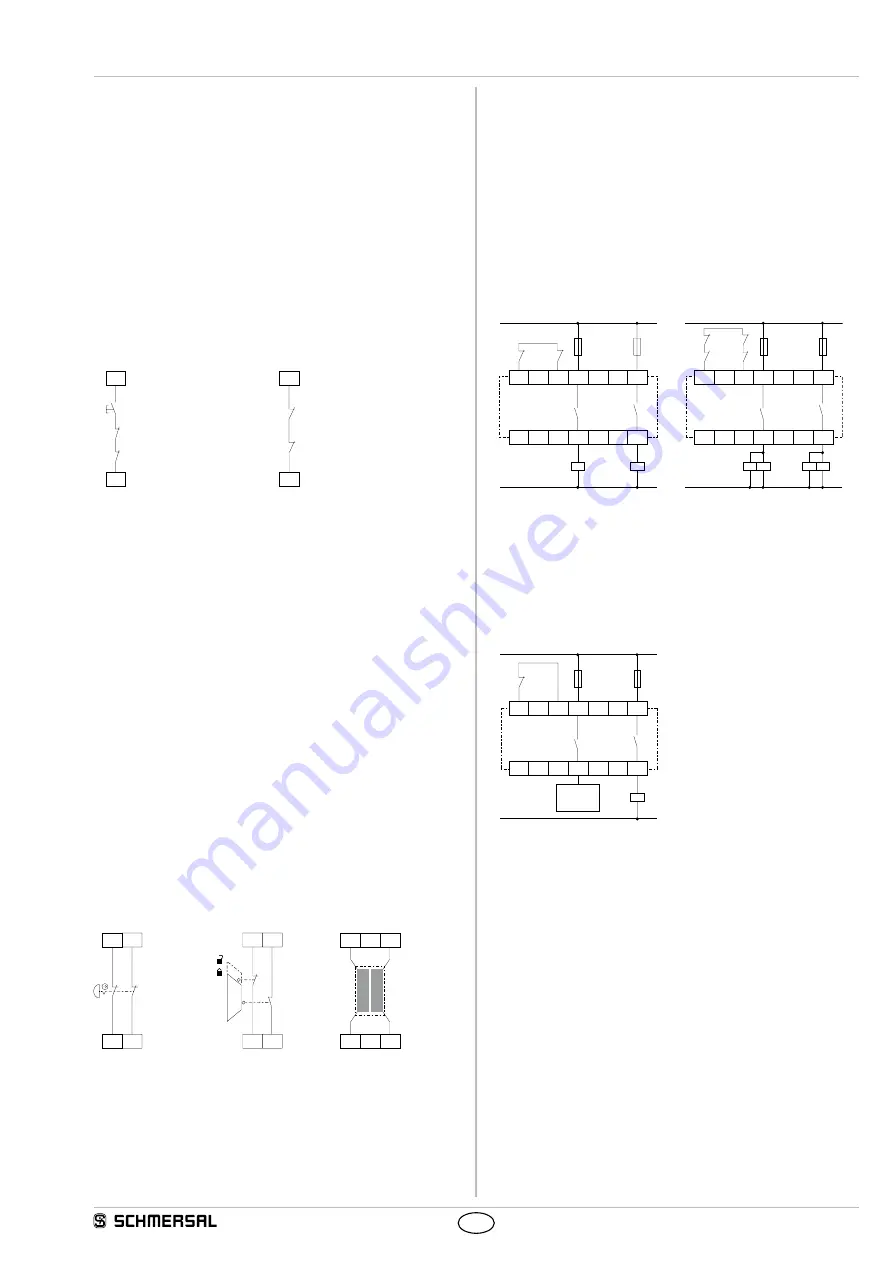
8.4 Actuator configuration
Single-channel control with feedback circuit (Fig. 8)
• Suitable for increase in capacity or number of contacts by means of
contactors or relays with positive-guided contacts.
•
S
= feedback circuit:
If the feedback circuit is not required, establish a bridge.
Dual-channel control with feedback circuit (Fig. 9)
• Suitable for increase in capacity or number of contacts by means of
contactors or relays with positive-guided contacts.
•
S
= feedback circuit:
If the feedback circuit is not required, establish a bridge.
X1
X2
23
13
24
14
K
C
K
A
S
L1
N
K
A
K
C
X1
X2
23
13
24
14
K
B
K
C
K
D
K
A
K
B
L1
N
K
A
K
D
S
K
C
Fig. 8
Fig. 9
Differential control with feedback circuit (see Fig. 10)
• Suitable for increase in capacity or number of contacts by means of
contactors or relays with positive-guided contacts.
•
S
= feedback circuit:
If the feedback circuit is not required, establish a bridge.
X1
X2
23
13
24
14
K
A
L1
N
K
A
S
a)
Fig. 10 a) Enabling signal controller


