schmersal SLG440 Operating Instructions Manual Download Page 16

16

EN

SLC-SLG440-D-EN

Operating instructions
Safety light grids

SLG440

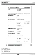
9.  EU Declaration of conformity

Name of the component:

SLC440
SLG440

Type:

See ordering code

Description of the component:

Safety light curtain / safety light grid

Relevant Directives:

Valid up to  
April 19, 2016

Valid as of  
April 20, 2016

Machinery Directive
EMC-Directive
RoHS-Directive

2006/42/EC
2004/108/EC

2011/65/EU

2006/42/EC

2014/30/EU

2011/65/EU

Applied standards:

EN 61496-1:2013,
EN 61496-2:2013,
EN ISO 13849-1:2008 + AC:2009,
EN 62061:2005 + A1:2013

Notiied body for the prototype test:

TÜV NORD CERT GmbH
Langemarckstr 20, 45141 Essen

ID n°: 0044

EC-prototype test certiicate:

44 205 13144608

Person authorized for the compilation  
of the technical documentation:

Oliver Wacker
Möddinghofe 30
42279 Wuppertal

K. A. Schmersal GmbH & Co. KG

Möddinghofe 30, D - 42279 Wuppertal
Postfach 24 02 63, D - 42232 Wuppertal 

Phone: 

+49 - (0)2 02 - 64 74 - 0 

Telefax:  +49 - (0)2 02 - 64 74 - 1 00
E-Mail: info@schmersalcom
Internet: http://wwwschmersalcom

Place and date of issue:

Mühldorf, February 24, 2016

Authorised signature

Klaus Schuster

Managing Director

Authorised signature

Christian Spranger

Managing Director

EU Declaration of conformity

Original

Safety Control GmbH
Am Industriepark 33
84453 Mühldorf / Inn
Germany

We hereby certify that the hereafter described components both in their basic design and construction conform 
to the applicable European Directives 

The currently valid declaration of conformity can be  
downloaded from the internet at wwwschmersalnet

Summary of Contents for SLG440

Page 1: ...About this document 1 1 Function 1 1 2 Target group authorised qualiied personnel 1 1 3 Explanation of the symbols used 1 1 4 Appropriate use 2 1 5 General safety instructions 2 1 6 Warning about mis...

Page 2: ...liability for damages and malfunctions resulting from defective mounting or failure to comply with this operating instructions manual The manufacturer shall accept no liability for damages result ing...

Page 3: ...restart interlock restart interlock 2 Input voltage HIGH active 11 30 V Input voltage LOW inactive 0 2 0 V Input current HIGH 3 10 mA Input current LOW 0 3 mA Functions automatic mode restart interloc...

Page 4: ...tputs OSSD s ON state after switch on of the operating volt age or an interruption of the protection field The system switches the outputs only to ON state when an external command device restart butt...

Page 5: ...is required The contactor control is not activated upon delivery The function is activated in parameter setting mode P 4 Connection EDM Wiring of the receiver Kn1 Kn2 auxiliary contact of the last sw...

Page 6: ...signalled in the following way 7 segment display LED OSSD ON red active LED OSSD OFF green active Parameter setting 1 When S1 is briely pressed the display shows repeatedly Parameter P 1 not active f...

Page 7: ...lication machine The safety inspections must be conducted regularly The SLG must not be exposed to inflammable or explosive gasses The connecting cables must be connected in accordance with the instal...

Page 8: ...eceive signal OK Beam b no receive signal Beam a and beam b receive signals OK Indication basic setting The signal strength is displayed per beam with two segments for the first a and the last b beam...

Page 9: ...tion from which the hazardous area is accessed To calculate the minimum distances of the safety guards with regards to the hazardous point the EN ISO 13855 and EN ISO 13857 must be observed If an over...

Page 10: ...0900 04 XX 300 1024 1043 258 5 217 5 L1 Mounting distance mm between floor and slotted hole centre short end cap L2 Mounting distance mm between floor and slotted hole centre diagnostic window Overal...

Page 11: ...reen outputs H signal 24V Red outputs L signal 0V Yellow setting mode restart interlock manual reset 24 5 12 5 15 0 1 The integrated status indication does not change the mounting dimen sion B or the...

Page 12: ...N 0 VDC BU Earth connection Restart interlock manual reset bridge 1 By bridging restart 2 pin 5 and DOUT pin 6 the restart interlock manual reset is activated Connect S1 to Pin1 Protective mode Automa...

Page 13: ...power supply see techni cal specifications which meets the CE Directives Low Voltage Directives A power downtime of 20 ms must be bridged 2 Presence of a voltage supply with correct polarity at the S...

Page 14: ...ring the first putting into operation 5 The cables the connectors the caps and the mounting angles are in perfect condition 5 5 Cleaning If the optics cover of the sensors is extremely soiled the OSSD...

Page 15: ...blanking area s of fixed or floating objects with the selected parameter setting fault elimination repeat configuration in the parameter setting possibly adjust P 1 P 2 P 3 Configuration error in para...

Page 16: ...13144608 Person authorized for the compilation of the technical documentation Oliver Wacker M ddinghofe 30 42279 Wuppertal K A Schmersal GmbH Co KG M ddinghofe 30 D 42279 Wuppertal Postfach 24 02 63...

Reviews: