4
Operating instructions
Safety light curtain/safety light grid
SLC440AS
SLG440AS
EN
SLC440AS Resolution 30 mm
Protected
height
[mm]
Beams
[lines]
Response
time
[ms]
Response time
Beam coding A
[ms]
Weight
[kg]
170
8
13
18
04
250
12
13
18
05
330
16
13
18
06
410
20
13
18
08
490
24
13
18
09
570
28
13
18
10
650
32
13
18
11
730
36
13
18
12
810
40
13
18
14
890
44
13
18
15
970
48
13
18
16
1050
52
23
30
17
1130
56
23
30
18
1210
60
23
30
20
1290
64
23
30
21
1370
68
23
30
22
1450
72
23
30
23
1530
76
23
30
24
1610
80
23
30
26
1690
84
23
30
27
1770
88
23
30
28
SLG440AS
Beams
[Number]
Beam
distance
[mm]
Response
time
[ms]
Response time
Beam coding A
[ms]
Weight
[kg]
2
500
13
18
090
3
400
13
18
135
4
300
13
18
150
The total reaction time of the safety guard consists of the
reaction times of the BWS, the maximum reaction time
of the AS-i safety system and the reaction time of the
actuators
Reaction time AS-i safety system:
≤ 40 ms
(AS-i slave + AS-i transm AS-i safety monitor)
2.7 Safety classification
Standards:
EN ISO 13849-1, EN 62061
PL:
e
Control Category:
4
PFH value:
≤ 5.17 x 10
-9
/ h
SIL:
suitable for SIL 3 applications
Service life:
20 years
2.8 Functions
The system consists of a receiver and a transmitter For the described
functions, no further switching elements are required The diagnostics
and the function selection are realised by means of the parameter
adapter (KA-0975), refer to chapter "Parameter setting"
The BWS is set to
„Automatic protection mode“
A possible restart interlock must be configured in the
AS-i safety monitor
The SLC has the following features:
• Blanking of fixed protection field areas
• Blanking of fixed protection field areas with movable edge region
• Blanking of movable protection field areas
The SLG has the following features:
• Blanking of movable protection field areas
Systems with alternative beam coding A can be ordered through
the type code (refer to type code).
2.8.1 Fixed blanking SLC440AS
The SLC440AS can blank stationary objects in the protection field
Multiple protection field areas can be blanked If small changes
are made within the fixed blanking area, each time 1 beam can be
additionally blanked to increase the tolerance See chapter Parameter
setting - Fixed blanking with movable edge regions (P 2)
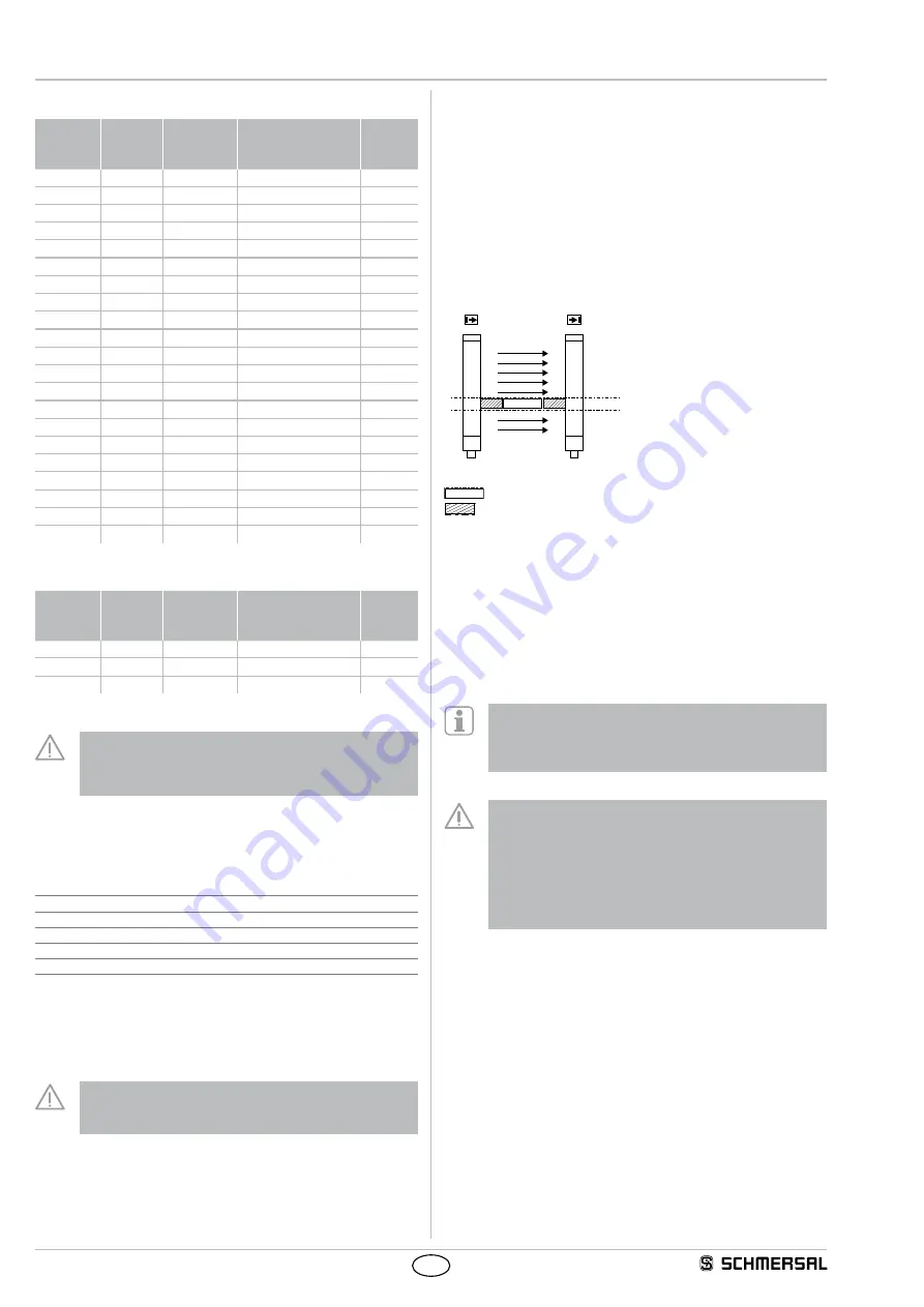
Fixed blanking area
E1
R1
Key
E1
R1
Object in protection field
E1
R1
Mechanical cover
The range of the fixed blanking can be arbitrarily chosen in the
protection field
The first beam line, which realises the optical synchronisation and is
located immediately behind the diagnostic window, cannot be blanked
The area of the fixed blanking must not be modified after the teach-
in process Any change of the area or removal of the object from the
protection field will be detected by the system As a result, the outputs
are disabled (locked) This locking can be neutralised by executing a
new teach-in process in accordance with the actual beam interruptions
The function is activated by means of the parameter setting
(P1) If the function is activated, the LED blanking in the
diagnostic window of the receiver starts flashing
See chapter Parameter settings
•
The remaining lateral areas must be protected against
intrusion by means of mechanical covers
•
The lateral covers must be fixed with the object
•
Partial covers are not authorised
•
After the fixed blanking, the protection field must be tested
by means of the test rod
•
The restart interlock function of the safety light curtain or the
machine must be activated
2.8.2 Fixed blanking with movable edge region SLC440AS
This function can compensate slight position changes of
a
fixed blanked
object with a change of +/- 1 beam This position change corresponds
to an amplitude of /- 10 mm resolution 14 mm and approx
+/- 20 mm resolution 30 mm upwards and downwards in the protection
field


