


8
Operating instructions
Safety sensor
CSS 34
EN
8. Appendix
8.1 Wiring examples
The application examples shown are suggestions. They however do not release the user from carefully checking whether the switchgear and its set-
up are suitable for the individual application.
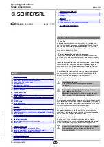
Wiring example 1: Series-wiring of the CSS 34 with conventional diagnostic output
The voltage is supplied to both safety inputs of the last safety sensor of the chain (considered from the safety-
monitoring module). The safety outputs of the first safety sensor are wired to the safety-monitoring module.
X1
Y1
X2
Y2
1
2
3
5
6
8
X1 X2 A1 A2
Y1
Y2
1
2
3
5
6
8
X1
4
Y1
4
Y1
X2
7
Y2
7
Y2
OUT
A1 A2
OUT
SPS/PLC
24 VDC
GND
CST 34-S-1
CSS 34
CST 34-S-1
CSS 34
Safety outputs → Evaluation
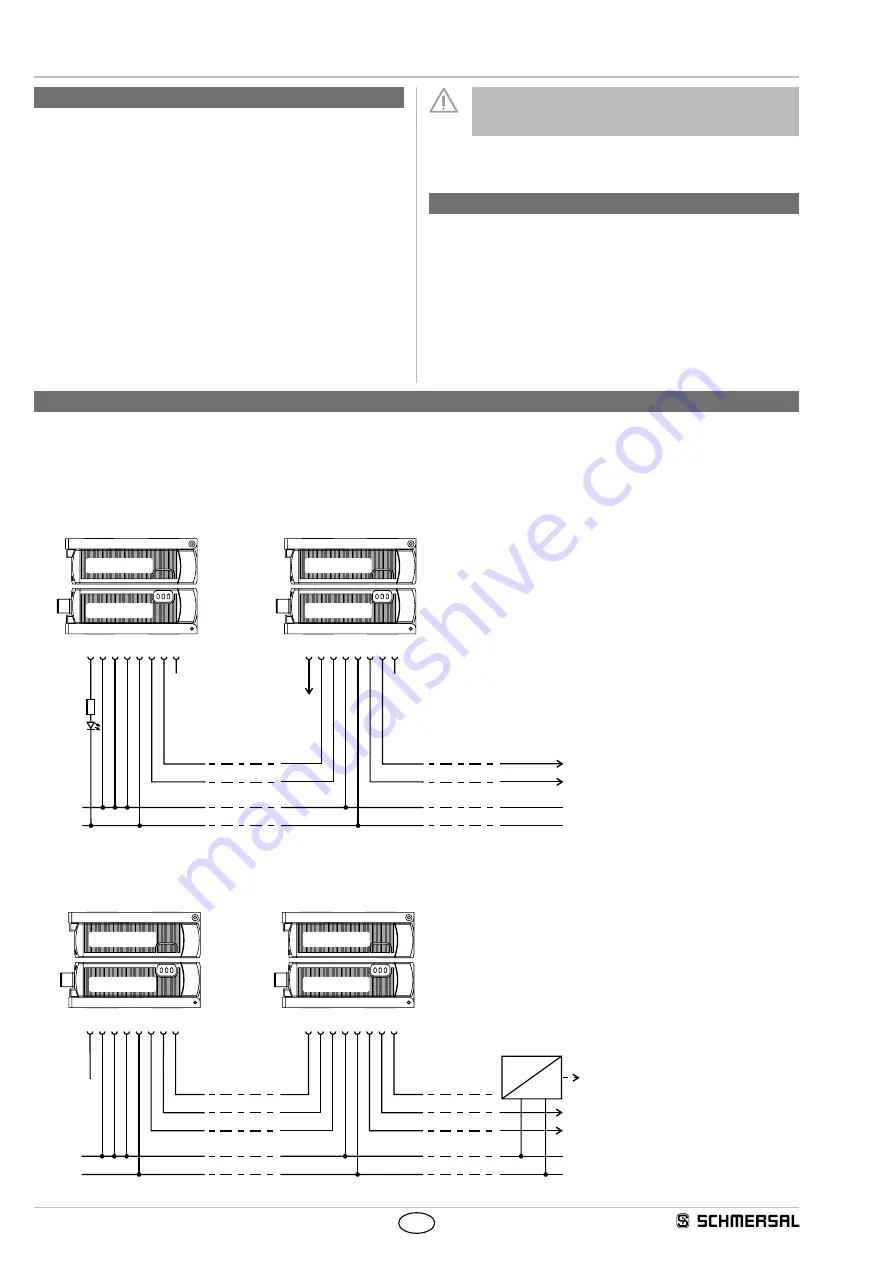
Wiring example 2: Series-wiring of the CSS 34 with serial diagnostic function
The safety outputs of the first safety sensor are wired to the safety-monitoring module.
The serial Diagnostic Gateway is connected to the serial diagnostic input of the first safety sensor.
Field bus
1
2
3
5
4
6
8
X1
Y1
X2
SD IN
SD OUT
A1 A2
1
2
3
5
4
6
8
X1
Y1
X2
7
Y2
7
Y2
SD IN
SD OUT
A1 A2
X1
Y1
X2
Y2
SD IN
SD OUT
Y1
Y2
SD IN
24 VDC
GND
CST 34-S-1
CSS 34
CST 34-S-1
CSS 34
Safety outputs → Evaluation
Gateway
6. Set-up and maintenance
6.1 Functional testing
The safety function of the safety components must be tested. The
following conditions must be previously checked and met:
1. Fitting of the sensor and the actuator
2. Fitting and integrity of the power cable
3. The system is free of dirt and soiling (in particular metal chips)
6.2 Maintenance
In the case of correct installation and adequate use, the safety sensor
features maintenance-free functionality.
A regular visual inspection and functional test, including the following
steps, is recommended:
• Check the fitting of the safety sensor and the actuator
• Remove possible metal chips
• Check the cable for damage.
Measures must be taken to protect against manipulation or
against the bypassing of safety device, for example, using an
extra actuator.
Damaged or defective components must be replaced.
7. Disassembly and disposal
7.1 Disassembly
The safety switchgear must be disassembled in a de-energised
condition only.
7.2 Disposal
The safety switchgear must be disposed of in an appropriate
manner in accordance with the national prescriptions and legislations.


