4
Operating instructions
Control panel with emergency stop
BDF200-SD
BDF200-FB
EN
3.4 Fixing
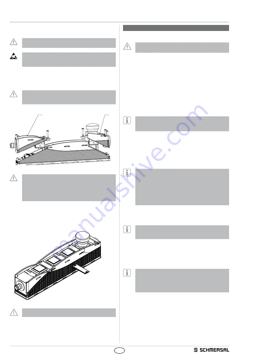
Remove the cover of the enclosure a and b (screws: Torx 10)
When opening the enclosure cover, please avoid damage to
the connecting cables
Caution!
Do not touch electrostatically loaded elements
Do not touch the printed circuit board
Use 2 x M5 cylindral screws ISO 4762 (DIN 912) for the assembly
After fitting, the cover screws must be tightened with a tightening torque
of 0.7 … 0.8 Nm.
When closing the enclosure cover, please observe that the
individual cables are not caught between the command
device and the contact element
a
b
When closing the enclosure cover, ensure that the
emergency stop module is flush with the bottom section and
that the cover screws are screwed in as far as they will go
The emergency stop safety function must be checked by
an appointed safety technician / safety representative once
successfully installed
3.5 Inscription plates
The marking on the inscription plates (included in delivery) is carried out
by colour change by laser The effects of heat may change the colour of
the surface
It must be ensured that the top is inscribed
4. Electrical connection
4.1 General information for electrical connection
The electrical connection may only be carried out by
authorised personnel in a de-energised condition
The safety outputs can be integrated into the safety circuit of the control
system To meet the demands of ISO 13849-1 for PL e / category 4,
the safety outputs of the control panel and control panel chain must be
connected to a monitor of the same category
Protection is not required when pilot wires are laid The cables however
must be separated from the supply and energy cables The max fuse
rating of a device chain for protection of the cable depends on the
cross section of the cables used
Requirements for the connected safety-monitoring module
• Dual-channel safety input, suitable for p-type devices
with normally-open function
Information for the selection of suitable safety-monitoring
modules can be found in the Schmersal catalogues or in the
online catalogue on the Internet: wwwschmersalnet
The control panel tests its safety outputs through cyclic deactivation
The safety-monitoring module therefore does not need to be equipped
with a cross-wire short detection The switch-off times must be tolerated
by the safety-monitoring module The deactivation time of the control
panel is also extended depending on the cable length and the capacity
of the cable used. Typically, a switch-off time of 250 μs is reached with
a 30-m connecting cable
Configuration of the safety-monitoring module
If the control panel is connected to electronic safety-
monitoring modules, we recommend a discrepancy time of
100 ms The safety inputs of the safety-monitoring module
must be able blanking a test impulse of approx 1 ms
The safety-monitoring module does not need to have a
cross-wire short monitoring function, if necessary, the
cross-wire short monitoring function must be disabled
4.2 Serial diagnostic SD interface
Cable design in case of serial diagnostics
When wiring SD devices, please observe the voltage drop
on the cables and the current carrying capacity of the
individual components
The wiring capacitance of the connecting cable of the safety sensor
must not exceed 50 nF
Depending on the strand structure, normal unshielded 200 m long
control cables LIYY 025 mm² to 15 mm² have a wiring capacitance of
approx 20 - 50 nF
Accessories SD interface
For ease of wiring and series-wiring of SD devices
considerable accessories are available
Detailed information is available on the Internet,
wwwschmersalnet


