schmersal AZM 200 D Operating Instructions Manual Download Page 4

4

Operating instructions

Safety switch with interlocking function

AZM 200 D

EN

3.3  Retrofit kit for Emergency release/Emergency exit

The retrofit kit is used for subsequent functional expansion of the safety 

switch.

Designation

Ordering code

Emergency release

RF-AZM200-N

103003543

Emergency exit

RF-AZM200-T

103004966

71

16

4.  Electrical connection

4.1  General information for electrical connection

The electrical connection may only be carried out by  

authorised personnel in a de-energised condition.

The power supply of the safety switch must provide protection against 

permanent overvoltage. To that effect, stabilised PELV supply units 

must be used. The safety outputs can be directly integrated in the 

safety circuit of the control system. For applications up to PL e / control 

category 4 to ISO 13849-1, the safety outputs Y1 and Y2 of the safety 

switch or safety switches must be connected to a safety-monitoring 

module of the same control category (refer to wiring example). 

The antivalent switching safety outputs Y3 and Y4 are suitable for 

requirements up to PL d / control category 3. To that effect, the outputs 

must be connected to a safety-monitoring module meeting at least the 

requirements of PL d / control category 3 to ISO 13849-1. The outputs 

cannot be wired in series.

Inductive loads (e.g. contactors, relays, etc.) are to be provided with 

suitable interference suppression circuitry.

Requirements for the connected safety-monitoring module:

•  Dual-channel safety input, suitable for 2 or 4 p-type semi-conductor 

outputs

Safety outputs Y1, Y2

The safety-monitoring module must tolerate internal functional with 

cyclic switch-off of the safety outputs Y1 and Y2 for max. 2 ms (typically 

< 1 ms). The switch-off stage of the test cycle is temporarily reduced 

by an active ohmic discharge of the cable. The safety-monitoring 

module does not need to have a cross-wire short monitoring function, if 

necessary, the cross-wire short monitoring function must be disabled.

Safety outputs Y3 and Y4

The safety outputs Y3 and Y4 are antivalent switching outputs.

A short concordance (< 50 ms) must be accepted, as the AZM 200 D 

might present small switching delays.
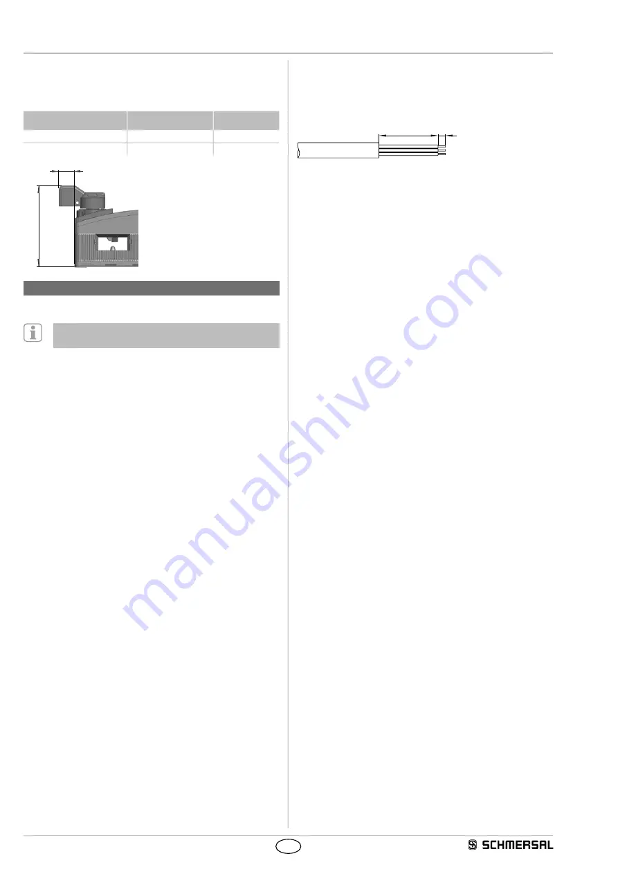
Cable

If the cable input is realised through a metric M20 cable gland, this 

gland must be dimensioned by the user so as to fit the cable used.  

A cable gland with strain relief and suitable IP protection class must  

be used.

40

5

The maximum cable length is 200 m (for ST2 M12 connectors approx. 

20 m depending on the cable section used for an operating current 

of 0.5 A). The maximum cable section is 1.5 mm², incl. conductuor 

ferrules. Prior to the connection, the cable must be stripped by  

40+5 mm and insulated by 5 mm.

Summary of Contents for AZM 200 D

Page 1: ...ted below or for the applications authorised by the manufacturer Detailed information regarding the range of applications can be found in the chapter Product description 1 5 General safety instructions The user must observe the safety instructions in this operating instructions manual the country specific installation standards as well as all prevailing safety regulations and accident prevention r...

Page 2: ...he safety guard is open or unlocked The safety switchgears are classified according to ISO 14119 as type 4 interlocking devices Safety switches with power to lock principle may only be used in special cases after a thorough evaluation of the accident risk since the safety guard can be opened immediately on failure of the power supply or upon activation of the main switch The user must evaluate and...

Page 3: ... 60947 5 3 PL d Control Category 3 PFH 1 x 10 7 h SIL suitable for SIL 2 applications Mission time 20 years 3 Mounting 3 1 General mounting instructions Please observe the relevant requirements of the standards ISO 12100 ISO 14119 and ISO 14120 For fitting the safety switch and the actuator two mounting holes for M6 screws with washers washers included in delivery are provided The safety switch mu...

Page 4: ...to ISO 13849 1 The outputs cannot be wired in series Inductive loads e g contactors relays etc are to be provided with suitable interference suppression circuitry Requirements for the connected safety monitoring module Dual channel safety input suitable for 2 or 4 p type semi conductor outputs Safety outputs Y1 Y2 The safety monitoring module must tolerate internal functional with cyclic switch of...

Page 5: ...t immediately affect the safe functionality of the safety switch will lead to a delayed shut down refer to table 2 After fault rectification fault at output Y1 or Y2 temperature fault the fault is acknowledged by opening and relocking the relevant guard door The safety outputs enable and allow a restart An interlocking chain must be permanently locked to enable the reactivation Automatic electroni...

Page 6: ...N3 IN1 IN2 SRB S12 A1 S22 A2 24VDC 0V S12 A1 S22 A2 24VDC 0V Table 1 the diagnostic function of the AZM 200 D safety switch System condition Solenoid control IN LED LED LED Safety outputs Diagnostic output Power to unlock Power to lock green red yellow Y1 Y2 Y3 Y4 OUT Safety guard open 24 V 0 V 0 V 24 V On Off Off 0 V 0 V 0 V 24 V 0 V Door closed actuator not inserted 24 V 0 V On Off Flashes 3 Hz ...

Page 7: ... output 4 6 VT 6 PK PK Y2 Safety output 2 7 RD 7 VT BU IN Solenoid control 8 PK 8 OR shielded RD LED LED 9 9 Key button Input output 10 10 Key button Input output 11 11 NC 12 12 Connector plug ST1 M23 8 1 pole Connector plug ST2 M12 8 pole Connector plug ST M23 12 pole 1 2 9 3 4 5 6 7 8 5 8 4 3 2 1 7 6 10 12 11 9 8 7 6 5 4 3 2 1 Connecting cables with female connector IP67 M23 8 1 pole 8 x 0 75 mm...

Page 8: ...romagnetic inter lock for safety functions Relevant Directives Machinery Directive EMC Directive RoHS Directive 2006 42 EC 2014 30 EU 2011 65 EU Applied standards EN 60947 5 3 2013 ISO 14119 2013 EN ISO 13849 1 2015 EN 61508 parts 1 7 2010 EN 62061 2005 AC 2010 A1 2013 A2 2015 Notified body for the prototype test TÜV Rheinland Industrie Service GmbH Am Grauen Stein 51105 Köln ID n 0035 EC prototyp...

Reviews: