Description of Functions
EN
· 30.30.01.02851 · 01 · 03/22
49 / 96
WARNING
By activating/deactivating the product, output signals lead to an action in the production
process!
Personal injury
Avoid possible danger zone.
Remain vigilant.
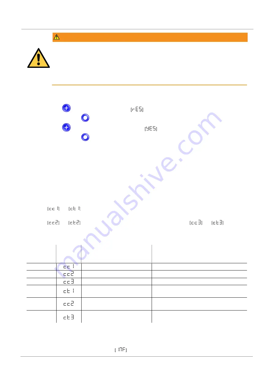
Below is a description of how to reset the area gripper to its factory settings using the display and operating element:
The EF menu is open.
1.
Use the
button to select the parameter
.
2.
Confirm using the
button.
3.
Use the
button to select the setting parameter
.
4.
Confirm using the
button.
The area gripper is reset to the factory settings.
The reset to factory settings function does not affect the following elements:
•
The counter readings
•
The zero-point adjustment of the sensor.
7.16
Counters
The area gripper has three internal, non-erasable counters and three erasable counters.
Counters 1
and
increase with every valid “Suction” signal pulse, and thus count the area gripper’s
suction cycles.
Counters 2
and
count the suction valve’s switching cycles, and counters 3
and
count the
CM events.
The average switching frequency can be determined using the difference between counters 1 and 2.
ISDU [Hex]
Display
code/param
eter
Function
Description
0x008C
Counter 1
Counter for suction cycles (suction signal)
0x008D
Counter 2
Counter for suction valve switching frequency
0x008E
Counter 3
Counter for condition monitoring events
0x008F
Counter 1, erasable
Counter for suction cycles (Suction signal) –
erasable
0x0090
Counter 2, erasable
Counter for suction valve switching frequency –
erasable
0x0091
Counter 3, erasable
Counter for condition monitoring events –
erasable
The counters can be displayed or read out from the INF menu using the parameters listed in the table, or via IO-Link.
Calling up the Counter Values
Select the counter you wish to see in the
menu.


