background image

Component Functions

EN-US · 30.30.01.02237 · 00 · 04/20

49 / 94

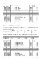
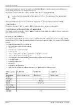
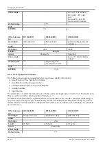
Unit

-

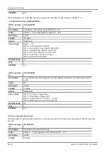
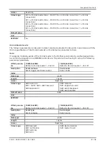
EEPROM

Yes

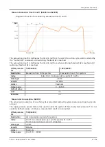
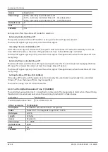
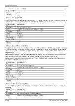
Offset parame-
ter

246 (0x00F6)

241 (0x00F1)

242 (0x00F2)

Description

Geo-location

Device Features

Equipment identifica-
tion

Index

-

Data type

char

uint8

char

Length

64 bytes

11 bytes

64 bytes

Access

Read/write

Read only

Read/write

Value range

-

Default value

***

-

***

Unit

-

EEPROM

Yes

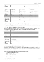
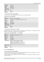
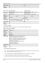
6.2.4   Access Rights: PIN Code for NFC Write Protection (0x005B)

The writing of changed parameters via NFC can be controlled using a separate PIN code. When delivered,
the PIN code is 000 and a lock is therefore not active.

The NFC PIN code can be changed only using this parameter.

When a PIN code is set between 001 and 999, the valid PIN must be entered for every subsequent write
process using a mobile NFC device so that the Compact terminal SCTSi accepts the changes.

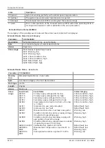
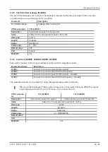
Parameter

91 (0x005B)

Description

PIN code: Pass code for writing data from NFC app

Subindex

Subindex data
type

uint16

Length

1 bytes

Access

Read/write

Value range

0: No PIN code
1 to 999: PIN code for NFC

Default value

0

Unit

-

EEPROM

Yes

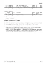
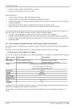
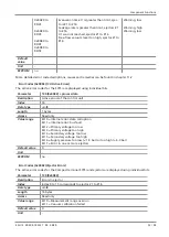
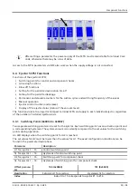
6.3   Device Status of the Whole Terminal SCTSi

Many parameters and values are measured with monitoring and diagnostic functions of the compact ter-
minal SCTSi (bus module and additional modules). These values are made available via the process data
and parameter data and are used for further diagnostics.

Device monitoring (determination of the required system parameters):

Current terminal operating voltages

Ejector evacuation times

Ejector air consumption data

Ejector leakage data
Summary of Contents for Compact Terminal SCTSi

Page 1: ...Compact Terminal SCTSi PROFINET EtherNet IP EtherCAT Operating Instructions WWW SCHMALZ COM EN US 30 30 01 02237 00 04 20...

Page 2: ...ished thereby Repro duction of the contents in full or in part is only permitted within the limits of the legal provisions of copyright law Any modifications to or abridgments of the document are proh...

Page 3: ...2 2 Bus Module Displays 13 3 3 Description of the Ejector 16 3 3 1 Ejector Variants 17 3 3 2 Ejector Displays and Operating Elements 19 3 4 IO Link Class B Master 19 3 4 1 Description 20 3 4 2 Display...

Page 4: ...Ejector 65 6 5 IO Link Master Functions 66 6 5 1 Process Data Management 66 6 5 2 IO Link Port Configuration 66 6 5 3 IO Link ISDU data management read write parameter data of IO Link devices 72 6 6 D...

Page 5: ...94 12 Troubleshooting 89 12 1 Help with Malfunctions 89 12 2 Error Codes Causes and Solutions 0x0082 90 13 Decommissioning and Recycling 91 13 1 Disposing of the Compact Terminal 91 13 2 Materials Us...

Page 6: ...d safe operation follow the instructions in the documents 2 Keep the technical documentation in close proximity to the product The documentation must be ac cessible to personnel at all times 3 Pass on...

Page 7: ...sult in minor or moderate injury if not avoided NOTE Indicates a danger that leads to property damage 1 5 Symbol This symbol indicates useful and important information This symbol represents a prerequ...

Page 8: ...vacuum for gripping and transporting objects when used in conjunction with suction cups Neutral gases are approved as evacuation media Neutral gases include air nitrogen and inert gases e g argon xeno...

Page 9: ...e or animals Evacuation of objects that are in danger of imploding 2 4 Personnel Qualifications Unqualified personnel cannot recognize dangers and are therefore exposed to higher risks 1 Task only qua...

Page 10: ...supply can be con nected centrally for all ejectors As an alternative it can also be connected separately for each ejector Each ejector has an autonomous energy and process control for monitoring the...

Page 11: ...rtant Notes A terminal always consists of a bus module and individual discs ejectors DI module IO Link master A maximum of four ejector individual discs can be used Identical individual discs must be...

Page 12: ...module max 6 6 IO Link master module max 2 7 Bus module with display 8 SCPSt ejector with display operating ele ment 1 to 16 9 Type plate 1 10 Pressure distributor with additional 1 4 thread compress...

Page 13: ...ltage Off No actuator voltage Green Actuator voltage OK Flashing green Actuator voltage not OK L1 and L2 Link Port X01 and Port X02 Off No PROFINET connection Green PROFINET connection established Fla...

Page 14: ...with data transfer NS Network status Off No voltage or no IP address Green Online one or more connections es tablished CIP class 1 or 3 Flashing green Online no connections established Red Duplicate...

Page 15: ...T device is in INIT state or no voltage Green EtherCAT device is in OPERATIONAL state Flashing green EtherCAT device is in PRE OPERA TIONAL state Green 1 flash EtherCAT device is in SAFE OPERA TIONAL...

Page 16: ...can also be a compressed air supply for each ejector An integrated sensor records the vacuum generated by the venturi nozzle The vacuum value is displayed via the LED bar and can be read out via the...

Page 17: ...event of a power failure or failure of the controller or its communication This also applies when the ejector was in the Venturi nozzle inactive state with the air saving function activated In this c...

Page 18: ...tion EJECTOR CONTROL Bit Ejector blow off Suction state Blow off state Undervoltage sensor or actuator voltage The blow off valve on the ejector is activated and deactivated using the blow off command...

Page 19: ...ector not blowing off Yellow Ejector blowing off 6 MANUAL MODE button Manual control of the suction and blow off ejector functions both the suction and blow off LEDs flash See ch 9 2 Manual Operation...

Page 20: ...ication status and the actuator supply voltage Up to four IO Link devices with the possible transmission speeds COM1 COM2 COM3 can be connected to each IO Link master All communication takes place via...

Page 21: ...O Link com munication Off No IO Link communication Flashing yellow slowly Ready to establish IO Link communication Flashing yellow quickly IO Link communication is be ing established with a device Per...

Page 22: ...State Description 2 1 3 1 LED assignment for the ports 1 Port X1 2 Port X2 3 Port X3 4 Port X4 2 LED status 1 Off No valid signal 0 V at input 1 Pin 2 of the corresponding port Yellow Valid signal 24...

Page 23: ...sensor supply voltage 24 V 5 A Supply voltage for actuator 24 V 20 to 10 VDC PELV1 Max permitted power consumption for actuator supply voltage 24 V 16 A Typ Max every 500 ms for 25 ms Power consumptio...

Page 24: ...tion IEC 61131 2 type 1 3 3 conductors Signal voltage 0 DIn Pin 2 and 4 3 V 7 V Signal voltage 1 DIn Pin 2 and 4 11 V 36 V Max permitted digital input voltage Pin 2 and 4 36 V Input current I_DIn Pin...

Page 25: ...vidual ejector SCPS 10 73 60 Individual ejector SCPS 15 73 65 Individual ejector SCPS 2 07 63 58 Individual ejector SCPS 2 09 73 60 Individual ejector SCPS 2 14 75 65 1 at 4 bar 4 3 2 Dimensions Table...

Page 26: ...230 g 150 g n 240 g a 160 g b 130 g with 10 to 16 ejector discs m approx 350 g 150 g n 240 g a 160 g b 130 g The letter n stands for the number of ejector discs installed in the terminal The letter a...

Page 27: ...Technical Data EN US 30 30 01 02237 00 04 20 27 94 4 3 5 Pneumatic circuit plans SCPSt NO SCPSt NC SCPSt 2 NO SCPSt 2 NC...

Page 28: ...Technical Data 28 94 EN US 30 30 01 02237 00 04 20 SCPSt IMP SCPSt 2 IMP...

Page 29: ...CTSi and output process data data to the Compact termi nal SCTSi Device description files are available for integration into a higher level controller The process data width is dependent on the actual...

Page 30: ...Q Pin 4 instead of configuring IO Link and reading or writing the status via process data The configuration is carried out by assigning the appropriate configuration module to the corresponding port...

Page 31: ...e in the overall Ethernet process data for the respective IO Link master port is listed in table 5 2 1 as Master x Port x Input and 5 2 2 as Master x Port x Output 5 2 2 Input Process Data The input d...

Page 32: ...tended Values 289 298 Extended Values Ejector 2 299 308 Extended Values Ejector 3 309 318 Extended Values Ejector 4 319 328 Extended Values Ejector 5 329 338 Extended Values Ejector 6 339 348 Extended...

Page 33: ...ge too high Bit 4 Secondary voltage too low Bit 5 Secondary voltage too high Bit 6 Supply pressure too low 1 9 bar or too high 6 3 bar Bit 7 Error in one or more ejectors CU CONDITION MONITORING Contr...

Page 34: ...V at Master 1 Port X2 Pin 4 Master 1 Port 3 digital input IO Link Master 1 Port X3 process data digital input 24 V at Master 1 Port X3 Pin 4 Master 1 Port 4 digital input IO Link Master 1 Port X4 proc...

Page 35: ...I module status Port X4 Pin 4 5 2 3 Output Process Data The output process data is used to control the SCTSi the IO Link class B master and the individual ejectors cyclically To determine the air cons...

Page 36: ...ector suction Bit 1 B01 Ejector blow off Bit 2 res Reserved Bit 3 res Bit 4 res Bit 5 res Bit 6 res Bit 7 res IO LINK MASTER 1 PORT OUTPUT ro Master 1 Port 1 IO Link output IO Link Master 1 Port X1 pr...

Page 37: ...Master 2 Port X4 Pin 4 5 3 Parameter data All parameters of the device can be read and partially written via acyclic communication This includes set values such as ejector H1 H2 thresholds hysteresis...

Page 38: ...le ments Get USINT Number of elements of the specified data type 4 Access rights of the instance Get Array of USINT Specifies the access rights for the instance Bit 0 1 read rights Bit 1 1 write right...

Page 39: ...tallation date char 1 16 rw 254 0x00FE 0 System configuration uint8 64 ro 354 0x062 0 Current system configuration char 128 ro Device Settings Offset Index Description Type Length bytes R W Dec Hex 2...

Page 40: ...o 515 0x0203 0 15 System vacuum for ejectors 1 to 16 uint16 16 x 2 ro 11000 11015 0x2AF8 0x2B07 0 Ejector extended values 1 to 16 uint16 16 x 2 ro Device Diagnostics Parameters Offset Index Descriptio...

Page 41: ...gin uint8 1 ro 10609 0x2971 Event Code uint8 1 ro 10610 0x2972 Event Number uint8 1 ro Parameters IO Link Master Device Process Data Offset Index Description Type Length bytes R W Dec Hex 10600 0x2968...

Page 42: ...s or ports the following offset addresses must be added Offset for Additional Ports Dec Port X1 Port X2 Port X3 Port X4 IO Link master 1 0 20 40 60 IO Link master 2 100 120 140 160 Example Process Dat...

Page 43: ...TSi functions as a passive NFC tag that can be read or writ ten by a read or write device which has NFC activated such as a smartphone or tablet Access to the Com pact terminal SCTSi parameters via NF...

Page 44: ...ata maximum or current Device Diagnostics Terminal status via status traffic light device status Terminal status via extended status signals extended device status Condition diagnostics of the bus mod...

Page 45: ...by writing parameter 0x0002 with a predefined value Offset parame ter 2 0x0002 Description System command triggers special features of the device Index Data type uint8 Length 1 bytes Access Write onl...

Page 46: ...or the sensor and actuator 6 2 2 Device Identification The Compact terminal SCTSi provides a range of identification data that can be used to uniquely identify a specific device All of these parameter...

Page 47: ...type char Length 14 bytes 2 bytes 10 bytes Access Read only Value range Default value Unit EEPROM Yes Offset parame ter 23 0x0017 24 0x0018 240 0x00F0 Description FW revision Application specific tag...

Page 48: ...on location Identification of the storage location Equipment labeling from the circuit diagram Installation date Geo location The parameters are ASCII character strings with the maximum length given i...

Page 49: ...he valid PIN must be entered for every subsequent write process using a mobile NFC device so that the Compact terminal SCTSi accepts the changes Parameter 91 0x005B Description PIN code Pass code for...

Page 50: ...nce PM Predictive maintenance to increase the performance and quality of the gripping systems 6 3 1 Device Monitoring Determination of the Required System Parameters The following system parameters ar...

Page 51: ...ctors Evacuation time t1 for ejectors Index Index 0 to 15 corresponds to ejector 1 to 16 Data type uint16 Length 32 bytes Access Read only Value range 0 65535 Default value Unit ms EEPROM no Measure A...

Page 52: ...nterrupted suction is required for at least 1 second after starting the suction i e the suction point must not be cov ered by a part Measured values below 5 mbar or above the switching point H1 are no...

Page 53: ...ters The individual values can each be read separately via separate parameters see above Offset parame ter 11000 0x2AF8 11015 0x2B07 Description Ejector extended values 1 16 Byte 1 10 Data type uint16...

Page 54: ...atus Event code Byte 3 4 Event category of current device status Data type uint16 Length 2 bytes Access Read only Value range Event Code 0x5100 0x5110 0x5112 0x1812 0x1802 0x1811 0x1000 0x8C01 0x180C...

Page 55: ...ption Active errors of the control unit Index 16 Data type uint8 Length 1 bytes Access Read only Value range Bit 0 Internal error data corruption Bit 1 Internal error bus fault Bit 2 Primary voltage t...

Page 56: ...t 4 Free flow vacuum too high Bit 5 Manual mode active Default value 0 Unit EEPROM no Offset parame ter 146 0x0092 Description CU condition monitoring part of processdata condition monitoring of contr...

Page 57: ...directly via the diagnostic sta tus within the integration in a SIEMENS controller via TIA portal without having to call up the following parameters individually Offset parame ter 10605 0x296D Refers...

Page 58: ...Index Data type uint8 Length 1 bytes Access Read only Value range 0x00 data valid write finished successfully 0x23 write failed write access locked 0x30 write failed parameter s out of range 0x41 wri...

Page 59: ...CTSi and apply to each individual ejector regardless of the number of installed ejectors discs 6 4 1 Switching Points 0x0064 to 0x0067 Two separate switching points can be set for the ejector Each swi...

Page 60: ...g on whether the air saving function is selected vacuum generation is interrupted The process data bit for H1 is set 6 4 2 Control Functions 0x006D The ejector allows you to conserve compressed air or...

Page 61: ...ys apply H1 h1 Control The ejector switches off vacuum generation when the switching point H1 is reached and switches it back on when the vacuum falls below the hysteresis point H1 h1 The switch point...

Page 62: ...The blow off starts with the blow off signal and is performed for the set time period Applying the blow off signal for a longer time does not lead to a longer blow off period The blow off signal is gi...

Page 63: ...nal non erasable counters and two erasable counters Parameter address Description 0x008C Counter for suction cycles Suction signal 0x008D Counter for suction valve switching frequency 0x008F Counter f...

Page 64: ...l signals may change manual mode Personal injury or property damage due to unforeseen work steps 4 There must be no people in the system s danger area while it is in operation In manual mode the Sucti...

Page 65: ...n the ejector for at least 3 seconds The Suction and Blow off LEDs cease to flash The ejector is in the Pneumatically OFF position A signal change suction blow off also ends manual mode 6 4 8 Changing...

Page 66: ...urthermore the byte order endianness for the corresponding Ethernet variant must be observed See 5 2 Process Data Process Data via Parameter Data Alternatively the process data can also be read writte...

Page 67: ...on the corresponding master port goes out DO digital output The port is configured as a digital output 24 V The output is activated or deac tivated depending on the lowest bit of the lowest output pro...

Page 68: ...Device Validation Offset parame ter 10406 0x28A6 Refers to IO Link master 1 Port X1 Description Cycle time Index Data type uint8 Length 1 bytes Access Read write Value range 0 65535 Default value 0x14...

Page 69: ...rerequisite To use data storage the Inspection Level parameter must be configured with at least TYPE_COMP You can define which of the two functionalities backup upload or restore download are activate...

Page 70: ...nnected but there is no valid data in the master The read parameters are permanently stored in the master The parameter data in the master can be over written by executing the Force upload of paramete...

Page 71: ...f the port as a dig ital output refers to GNDS pin 3 Offset parame ter 10414 0x28AE Refers to IO Link master 1 Port X1 Description Power on off switch L pin 1 Index Data type bool Length 1 bytes Acces...

Page 72: ...of the IO Link master process data lowest bit lowest byte 6 5 3 IO Link ISDU data management read write parameter data of IO Link devices IO Link ISDU data management describes the possibility of rea...

Page 73: ...e 2 0x0002 W 10201 0x27D9 Request Subindex ISDU subindex of the device 1 0x00 W 10202 0x27DA Request RW 0 Read 1 1 W 10205 0x27DD Request Trig ger 1 Start inquiry 1 1 R 10206 0x27DE Request Error 0 Re...

Page 74: ...re gardless of the data width actu ally used 232 01 02 03 W 10205 0x27DD Request Trig ger 1 Start inquiry 1 1 R 10206 0x27DE Request Error 0 Request was successfully sent 1 Request was aborted because...

Page 75: ...e IO Link interface specifi cation Default value Unit EEPROM no EtherNetIP To access the ISDU parameters of an IO Link device connected to the IO Link master an object an in stance and an attribute mu...

Page 76: ...as 8 digital inputs 2 inputs per port A maximum of 6 DI modules can be installed on one terminal Thus up to 48 digital inputs are possible on the compact terminal Status via Input Process Data EtherNe...

Page 77: ...Component Functions EN US 30 30 01 02237 00 04 20 77 94 Bit 5 DI module status Port X3 Pin 4 Bit 6 DI module status Port X4 Pin 2 Bit 7 DI module status Port X4 Pin 4 Default value Unit EEPROM no...

Page 78: ...bH 7 2 Removing the Packaging The Terminal is delivered in a cardboard box NOTE Sharp knives or blades Damage to components and packaging 4 Ensure that no components are damaged while opening the pack...

Page 79: ...ate installation space in the area where the product will be installed 8 2 Mounting The SCTSi may be installed in any position 5 1 2 3 4 8 9 6 7 1 Compressed air connection 1 4 thread 2 M12 D electric...

Page 80: ...mpressed air connection 3 1x vacuum air connection per ejector disc marking 2 The compressed air connector with the plug connector 8 6 or 1 8 thread is marked with the number 1 on the ejector disc 4 C...

Page 81: ...al changes on the overall system NOTE Incorrect connection with the IO Link class B port Damage to the IO Link master or periphery 4 When operating the IO Link class A switch with an IO Link master wi...

Page 82: ...s module EtherCAT OUT port 3 M12 D electrical connection socket for Ethernet Port X01 crossover x Labeled with X01 on bus module EtherCAT IN port Prepare the connection cable 1 Fasten the connecting c...

Page 83: ...coded M12 Socket for Industrial Ethernet M12 D socket PIN Symbol 2 1 4 3 1 TX 2 RX 3 TX 4 RX Thread FE 8 4 3 IOL Master Module Mounting the Connection Cable Mount the connection cable to the IOL mast...

Page 84: ...on cable to the DI module The figure shown here is an example Depending on the design of the terminal one to six DI modules are installed DI module Port X1 Port X2 Port X3 Port X4 Prepare the connecti...

Page 85: ...aust air flow 4 Wear eye protection CAUTION When the system is started in automatic operation components move without ad vanced warning Risk of injury 4 Ensure that the danger zone of the machine or s...

Page 86: ...ere must not be carried out by the operator of the product without consulting Schmalz 10 2 Replacing the Silencer When the silencer is open a heavy infiltration of dust oil and so on may contaminate i...

Page 87: ...primary spare and wearing parts Part no Designation Legend 10 02 02 04141 Silencer insert W 10 02 02 03376 Screen S 10 02 02 04152 Insulating plate W Legend Wearing part W Spare part S 4 When tighten...

Page 88: ...p Sealing cap for unused M12 socket IP67 21 04 05 00080 M12 connection cable M12 5 pin socket with open cable end 5 m connection cable for connecting components to the IO Link master and DI modules 21...

Page 89: ...is created too slowly Press in screen in contaminated 4 Replace screen Silencer is dirty 4 Replace the silencer Leakage in hose line 4 Check hose connections Leakage at suction cup 4 Check suction cu...

Page 90: ...eck power supply unit and power load 2 Increase supply voltage Bit 3 Overvoltage US Sensor supply voltage too high and outside the permit ted range 1 Check power supply unit 2 Reduce supply voltage Bi...

Page 91: ...1 Disposing of the Compact Terminal 13 2 Materials Used Component Material Housing PA6 GF PC ABS Inner components Aluminum alloy anodized aluminum alloy brass galvanized steel stainless steel PU POM S...

Page 92: ...ls the following applicable EC directives 2006 42 EC Machinery Directive 2014 30 EU Electromagnetic Compatibility The following harmonized standards were applied EN ISO 12100 2010 Safety of Machinery...

Page 93: ...30 30 01 02237 00 05 20 93 94...

Page 94: ...J Schmalz GmbH EN US 30 30 01 02237 00 04 20 Subject to technical changes without notice...

Reviews: