MANUAL
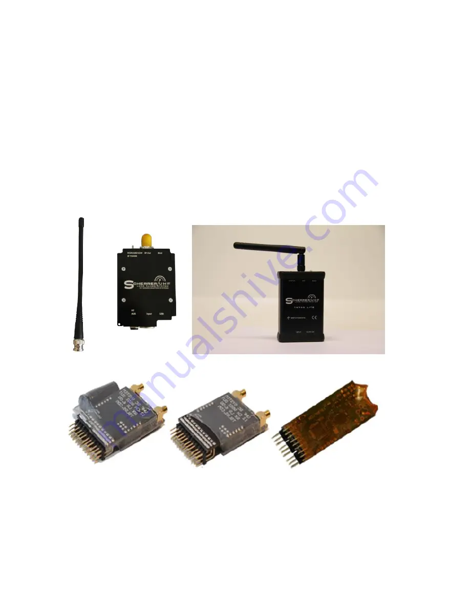
Transmitter, Pro & Lite
Receivers, Long Range & Normal range
Rev 1.0
Rev Date. 09/03/2016
Page 1: ...MANUAL Transmitter Pro Lite Receivers Long Range Normal range Rev 1 0 Rev Date 09 03 2016 ...
Page 2: ... connectors Tx700Pro 4 Tx700Lite 4 Hardware specifications 5 Tx700Pro 5 Tx700Lite 6 TX BATTERY LIFE 6 Physical Dimensions 7 Tx700Pro 7 Tx700Lite 7 Legal Information 7 Adapter wiring 7 Binding in details 8 Change unique ID code 8 Tx700Pro 8 Tx700Lite 8 Output Power selection button 9 Tx700Pro 9 Failsafe 9 ...
Page 3: ...ow to get best range 13 LED indicator 13 Range Check 13 Known Limitations 14 Foreword Receivers 15 Physical and technical specifications 15 Rx700 Normal Range 15 Rx700 Long Range 16 Binding 17 Failsafe foreword 17 The 3 Failsafe in detail 17 Ch12 PPM options 18 RSSI output 19 Connectors Servo 19 Serial Debug Output 19 Special Features Configurations 21 Channels on Normal Range 22 ...
Page 4: ...st which contains all kind of questions we have received both simple and more technically oriented Foreword Transmitter Here you will find the information which is needed to make your transmitter perform at the very best both for Tx700Pro and for the Tx700Lite Notice if the Pro or the Lite is not listed under a subject it means that it s the same for both Technical Specs Tx700Pro RF Output power 5...
Page 5: ...time or variable Positive or Negative polarisation The special double speed Futaba PPM signal is also accepted Auto detects and auto handle The main PPM signal must contain from 4 12 servo channels if main PPM signal has under 4ch it will be refused Note Graupner call each way a servo travel for a channel so in Graupner terms a 24 Channel setting handle 12 servos and is what we call a 12 channel s...
Page 6: ...acker PPM input shorted HT The Ring of the connector is AUDIO input from the wireless video system receiver Ground is common for both signals Shielded cables are recommended to avoid cross talk Hardware specifications Tx700Pro Supply voltage 5 25V for 500mW power Supply voltage 6 25V for 500mW 1000mW 2000mW power Supply power usage is 3 times the transmit power ...
Page 7: ...member to keep a good safe margin some batteries like LIPO do not like to be fully empty When using the power up feature input supply power will also go up The unit has about 30 40 efficiency so an easy rule is the input usage is 3 times as much power as the output power At 2W RF out the TX unit consume almost 6W this means 4W is radiated as heat The TX unit can deliver 500mW out at only 5V as sup...
Page 8: ... frequency hopping random sequence with very short time slots The time pr channel is only 15mS which means it apply to the 10mW pr average channel regulation in EU and many other areas This means the 500mW peak setting can be used legally without any radio amateur licence Note The Tx700Lite is CE approved and certified Adapter wiring Futaba JR Graupner Multiplex Naked only for Tx700Pro ...
Page 9: ...response 9 With TX on try to power OFF and ON the Rx and prove it lock to the Tx very fast after power on Instruction video on how to bind and store failsafe http www youtube com channel UCS2wXoorQHQaYmoSLE5_esg If you use external battery for the LRS TX then the binding procedure is a little bit different leave the RC unit on ALL the time and connected to the LRS TX the power on off to the TX as ...
Page 10: ...afe into the receiver When the button is pressed while the TX is powered on it s in the binding process When the TX is in normal flight mode the button is used to store failsafe The failsafe procedure is explained on page 18 Compatibility TX RX All versions of TSLRS RX units can be binded and work together with any versions of TSLRS TX units Since the over air signals are kept the same from the ve...
Page 11: ... free channels to use Then the two HT signals will be merged into channel 10 and 11 leaving channel 12 free to use for the main PPM The reason for this is easy to understand look at the receivers the channel 12 connector can be either PPM out or servo channel 12 out the different output mode is configured on the RX in case you need PPM out and use a HT at the same time you need off course the HT s...
Page 12: ...11 Tx700Lite With the Tx700Lite the head tracker input is integrated in the cable ...
Page 13: ...erface for UAV systems live 2 way data is then possible Voltage monitor with audio alarm THIS SECTION WILL BE UPDATED WHEN THE OPTION BOARD IS RELEASED Modem Setup Option Board Tx700Pro The Audio signal is 1200 Baud FSK from a video receiver the level can be from 200mV to 2000mV adjustable on the upgrade board trimmer adjust trimmer for carrier LED LIT find the two points where the LED is not lit ...
Page 14: ... the range This means also it is very easy to detect using range checks LED indicator Constant light PPM ok power supply ok Blinking LED Power supply ok but no valid PPM No Light No power supply voltage Range Check Can be done just like any conventional RC systems and please follow the following steps 1 Unmount the TX antenna and set it to low power 2 Expect 4 10 meters of range 3 Check you have s...
Page 15: ...he distance as height For example at 3 km 1 8mile distance stays 300 meters 984 feet up to get full range The Tx700Pro with will provide you with a signal to 100km 62 miles range depending on power selection and on which receiver is used This Tx700Lite with 500mW will provide you with a signal to 25 km 15 5 miles range depending on which receiver is used ...
Page 16: ...Input supply voltage range 4 10V Servo signal pulse output 3 3V positive Radio band 433 444 MHz multi band and multi frequency hopping system Temperature range 40C to 70C tested Receiver 8ch optimized input filter so it can co exist with strong 2 4 GHz on board video transmitters Wire antenna mounted directly on the Rx The extra pin in ch 12 connector is RSSI out Ch 12 connector is also PPM out wh...
Page 17: ... uses the best signal Two MCX connector coax dipole wire antennas come with each RX t Weight 5 4 grams each The extra pin in ch 12 connector is RSSI out It s now buffered so loading of the RSSI out is uncritical 1k ohm Zout It is also filtered to avoid less jumpy OSD readings CH 12 connector is also PPM out when 12ch are used auto mode is the default PPM out is the same as sum signal and this is o...
Page 18: ...o program the plane to shut of motor and turn slowly to the left side Some FPV UAV systems can use other settings the user should know what is best for his usage Always test if it s working as expected before a flight Test if recall the wanted function and recover again when the TX is powered back on The 3 Failsafe in detail The normal kind of failsafe is one set of servo positions stored in the r...
Page 19: ...l be recalled and it will simply hold last known good position of all servos To clear the failsafe memory hold the button for 5 sec A little side note on failsafe storing The Receiver will lose radio link and recall failsafe settings while you activate a storing The reason is the kind of memory used for this is a bit slow and while the CPU waits for the saving it s not able to maintain a perfect h...
Page 20: ...om RX to RX so you must perform a new calibration if you swap a receiver in your system Connectors Servo Look carefully at the connector pins and the PCB The edge rows are all GROUND the centre row are 5V and all top pins are the servo channels out Serial Debug Output The upgrade connector pin out 1 GROUND 2 3 6 are not connected 4 Radio data do not connect anything to this pin in flight mode 5 De...
Page 21: ...nd will be zeroed again at next power up so it is possible to land connect to a PC via serial port converter and see the values for the flight before you power off the RX The serial debug can also be use full to test failsafe storing and recalling it write in clear text what it is doing And it is also active during power up and under special mode setting configurations ...
Page 22: ...tween the two signals they are now shorted together Power up the RX See LED D1 is lit this one is closest to same side as ch6 Now you stored a permanent setting PPM out even if you use 12channels Power off Remove jumper Connect your servos Test all works POWER OFF Connect a 2 54mm 2 pin jumper a short circuit connection on servo channel 7 8 YES between the two signals they are now shorted together...
Page 23: ...the ch12 connector after a setting change or PPM timing change or number of channels assigned you must always perform a bind and store failsafe and test all settings works Channels on Normal Range Notice a channel 9 and 10 on the board if you wish to get more of you receiver Connect your power and ground to one of the other channels pins and then solder the servo control to the 9 or 10 channel pad...
Page 24: ...rom the coax There are no rules of how much of a distance but 3 5 cm is normally used RX antennas always have to mount with a 90 degree from each other With this setup there will be no lost spots See this example with an airplane The antennas are the red lines ...
Page 25: ...24 Bad antenna position ...
Page 26: ... www ftdichip com Drivers VCP htm Then download mcuboot original version some users might find version 1 3 works better if win7 or win8 http webx dk rc uhf link3 mcuboot e_x_e If this version don t work with your version operating system please try this mcuboot version 1 3 http webx dk rc uhf link3 mcuboot13 e_x_e Rename e_x_e extension to exe this mcuboot exe is made using Borland some PC s might...
Page 27: ...e to the HEX file you got via email using OPEN Remember the TX hex is for TX unit and the RX hex is for the RX File is accepted and loaded pull down in window so you can see the black status area click CONNECT ...
Page 28: ...27 Mcuboot now instruct you to cycle power supply they means actually you POWER UP RX or TX unit NOW Now you should be connected to the secret boot loader program ...
Page 29: ...tures of your new software so you know how to use it You must expect to perform new bind and new store failsafe after an upgrade Option Board for RX LR 7 01 The option board contains a data modulator so live flight data from the OSD is modulated into audio that is then transferred to ground station via the video links audio channel This option board is ONLY compatible with RX LR 7 01 and up THIS S...
Page 30: ...ach antenna connector The normal operation of the LED s are during flight and installation to show what antenna signal is the strongest since that is the selected signal FAST Blinking LED during power up indicate search mode FAST Blinking LED during flight indicates failsafe is recalled and search mode is now running ...
Page 31: ...ing the 500mW transmitter used for my long range system LRS RX the receiver located in the plane this receiver is connected directly to servos and 5V supply RSSI received signal strength indication is often an analogue voltage that goes up or down depending of radio signal level in a receiver Video TX Video transmitter located on a plane car boat helicopter or whatever often using 900 1300 2400MHz...
Page 32: ...es Virtual Reality experience to FPV FPV First Person View like pilot view out the front window UAV Unmanned Aerial Vehicle a UAV is a fully computer guided plane not a radio controlled plane if RC ed it is an FPV or just a normal RC plane Trainer Most advanced RC units have trainer connectors with PPM in out so they can be connected via a cable to a student RC unit Student Most advanced RC units ...
Page 33: ...le cells like normal alkaline types Today more new and fancy battery types like lipo and lion and such can also be used if receiver and servos can handle the different voltage range they provide Fading when the distance and positions and angles of a wireless system is changed the radio signal will also change Multipath Fading A direct signal and a reflected signal hit receiver antenna with 180 deg...
Page 34: ...eceivers away from all electronics in general speed controllers and switch mode supplies are known to be able to jam Electric Motor controller a range check must prove no degrade change when motor is off halve full power this also apply for gasoline and methanol engines Transmitters for live video or data back telemetry will always have harmonics like 2x 3x and so on of their wanted frequency the ...
Page 35: ...is smart to try locate a problem Switch mode it is often seen SBEC or other switch mode regulators are designed to be cheap and have no really good filter extra 100uH coils and 470 1000uF on the input and output might help input is just as important as the output Shielding some devices radiate magnetic pulses specially SBEC and cameras if they are contained in a closed metal case the problem will ...
Page 36: ... to a vertical the link loss will have an added extra loss of 26dB If a circular left is talking to a circular right the link loss will have an added extra loss of 26dB If a circular left is talking to a vertical or horizontal the link loss will have an added extra loss of 3dB This is why it is smart to combine a horizontal or vertical often mounted in a plane with a circular receiver on the groun...
Page 37: ...higher frequencies so a longer range is easier to get using lower frequencies Gain Adding more antenna gain will only make the beam more narrow point the antenna right and you get more range point the antenna wrong and you lose signal Any gain over 8 10dB will be hard to point to a moving target like a plane you need a tracker system or a cheap friend that will work for free to point the antenna A...