Firmware Design
P746/EN FD/G31
MiCOM P746
(FD) 9-
13
2.8
Auxiliary power supply
The three input voltage options are the same as for main supply. The relay board is provided
as an alone board.
2.9 IRIG-B
board
The IRIG-B board is an order option that can be fitted in the P746 to provide an accurate
timing reference for the relay. This is available as a modulated or de-modulated option
depending on the requirements. The IRIG-B signal is connected to the board via a BNC
connector on the back of the relay. The timing information is used to synchronize the relay’s
internal real-time clock to an accuracy of 1ms in the case of modulated. The internal clock is
then used for the time tagging of the event, fault maintenance and disturbance records.
2.10
Second rear communications
On ordering this board within a relay, both 2
nd
rear communications will become connection
and setting options. The user may then enable either one, or both, as demanded by the
installation.
There is a hardware option of a second rear communications port, which will run the Courier
language. This can be used over one of three physical links: twisted pair K-Bus (non-polarity
sensitive), twisted pair EIA(RS)485 (connection polarity sensitive) or EIA(RS)232.
The second rear comms. board and Ethernet board are mutually exclusive since they use
the same hardware slot. For this reason two versions of second rear comms. board are
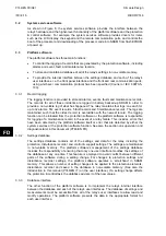
available; one with an IRIG-B input and one without. The physical layout of the second rear
comms. board is shown in Figure .
P2083ENa
Language:
Courier always
Physical links:
EIA 232
or
EIA 485 (polarity sensitive)
or
K-Bus (non polarity sensitive)
SK5
SK4
Physical links are s/w selectable
Optional IRIG-B
Courier Port
(EIA232/EIA485)
Not used (EIA232)
FIGURE 7: REAR COMMS. PORT
FD
Summary of Contents for MiCOM P746
Page 4: ......
Page 5: ...Pxxx EN SS G11 SAFETY SECTION...
Page 6: ......
Page 8: ...Pxxx EN SS G11 Page 2 8 Safety Section BLANK PAGE...
Page 16: ...P746 EN IT G31 Introduction MiCOM P746...
Page 18: ...P746 EN IT G31 Introduction IT 1 2 MiCOM P746 IT BLANK PAGE...
Page 26: ...P746 EN TD G31 Technical Data MiCOM P746...
Page 38: ...P746 EN GS G31 Getting Started MiCOM P746...
Page 78: ...P746 EN ST G31 Getting Started MiCOM P746...
Page 80: ...P746 EN ST G31 Settings ST 4 2 MiCOM P746 ST BLANK PAGE...
Page 112: ...P746 EN ST G31 Settings ST 4 34 MiCOM P746 ST BLANK PAGE...
Page 114: ...P746 EN OP G31 Operation MiCOM P746...
Page 136: ...P746 EN OP G31 Operation OP 5 22 MiCOM P746 OP BLANK PAGE...
Page 138: ...P746 EN AP G31 Application Notes MiCOM P746...
Page 142: ...P746 EN AP G31 Application Notes AP 6 4 MiCOM P746 AP BLANK PAGE...
Page 194: ...P746 EN AP G31 Application Notes AP 6 56 MiCOM P746 AP BLANK PAGE...
Page 196: ...P746 EN PL G31 Programmable Logic MiCOM P746...
Page 238: ...P746 EN MR A11 Measurements and Recording MiCOM P746...
Page 240: ...P746 EN MR A11 Measurements and Recording MR 8 2 MiCOM P746 MR BLANK PAGE...
Page 258: ...P746 EN FD G31 Firmware Design MiCOM P746...
Page 280: ......
Page 348: ...P746 EN MT A11 Maintenance MiCOM P746...
Page 350: ...P746 EN MT A11 Maintenance MT 11 2 MiCOM P746 MT BLANK PAGE...
Page 364: ...P746 EN MT A11 Maintenance MT 11 16 MiCOM P746 MT BLANK PAGE...
Page 366: ...P746 EN TS G31 Troubleshooting MiCOM P746...
Page 368: ...P746 EN TS G31 Troubleshooting TS 12 2 MiCOM P746 TS BLANK PAGE...
Page 382: ...P746 EN SC G31 SCADA Communications MiCOM P746...
Page 424: ...P746 EN SC G31 SCADA Communications SC 13 42 MiCOM P746 SC BLANK PAGE...
Page 426: ...P746 EN SG F21 Symbols and Glossary MiCOM P746...
Page 438: ......
Page 440: ...P746 EN IN G31 Installation IN 15 2 MiCOM P746 IN BLANK PAGE...
Page 468: ......
Page 470: ...P746 EN HI G31 Remote HMI HI 16 2 MiCOM P746 HI BLANK PAGE...
Page 500: ...P746 EN HI G31 Remote HMI HI 16 32 MiCOM P746 HI BLANK PAGE...
Page 502: ......
Page 504: ...P746 EN CS A11G31 Cyber Security CS 17 2 MiCOM P746 CS BLANK PAGE...
Page 524: ...P746 EN VH G31 Firmware and Service Manual Version History MiCOM P746...
Page 529: ......


