13
MPS4264
Section 3: Operation
SECTION 3: OPERATION
Unpack & Inventory
When you first unpack the MPS4264 module, begin by
inspecting and inventorying the contents of the package.
If any visible damage is immediately noticed or if any
contents are missing, contact Scanivalve before proceeding.
As a minimum, MPS4264 modules are shipped with the
following contents:
1. MPS4264 module
2. Protective case
3. 155625 Power cable with flying leads
4. 156110 Ethernet RJ45 adaptor cable
5. MPS4264 resource CD
Mounting
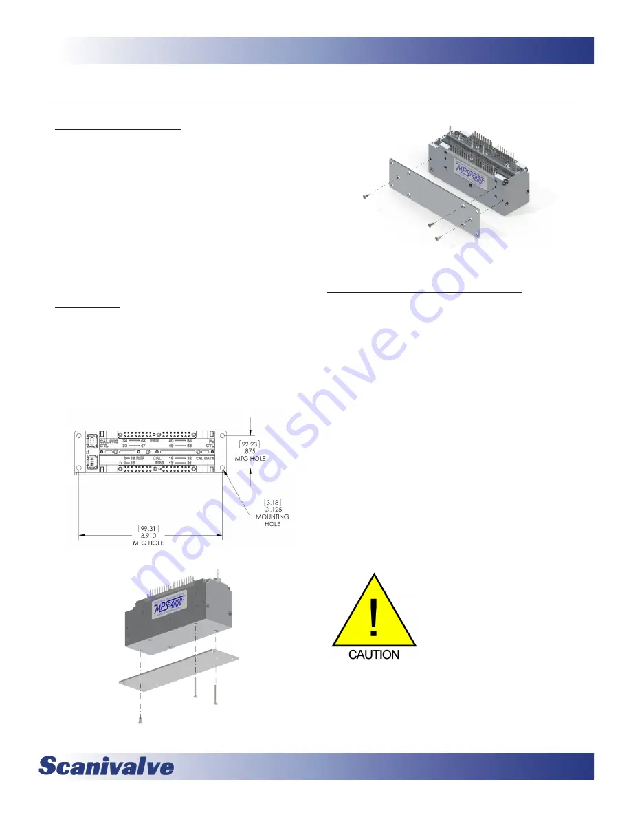
The MPS4264 includes a stainless steel mounting plate.
Using three #
2-56
screws it can either be mounted to the
bottom of the module or to the side. The mounting plate is
0.060” (1.5mm) thick with four 0.125” (3.1mm) holes in it.
See Figure 3-1 for hole spacing, and Figures 3-2 and 3-3 for
instructions for attaching the mounting plate to the MPS
module. The MPS can be mounted in any orientation.
Figure 3-1: Mounting Plate Dimensions
Figure 3-2: Mounting Plate, Bottom
Figure 3-3: Mounting Plate, Side
Environmental Considerations
The MPS4264 series is designed to withstand normal
industrial, flight test, educational, wind tunnel or similar
applications. The module is not water proof and it should
be protected from any splash, spray or mist. If any mois-
ture gets spilled or splashed on the MPS module, wipe it
dry immediately to prevent damage to the module.
The MPS module should not be mounted in a location
where it may be subjected to extreme temperature shifts
or ambient temperatures outside limits defined in “Section
1: Specifications” on page 7. Keep in mind that the
internal temperature of the module will run approximately
15°C - 20°C warmer than ambient temperature but this is
accounted for in the calibration tables. The temperature
specification is with regards to the ambient temperature.
If the MPS module needs to be used in an environment
outside of the guidelines above it should be installed in
a Thermal Control Unit (TCU). This is a rugged enclosure
incorporating a heater or cooling fittings in order to protect
the MPS module.
CAUTION! Mounting the MPS
module inadequately or in an envi-
ronment that does not conform to
the recommendations can results in
permanent damage to the module.
Summary of Contents for MPS4264
Page 1: ...MPS4264 Miniature Pressure Scanner Hardware and Software Manual Software Version 2 07...
Page 2: ......
Page 3: ......
Page 6: ...INTENTIONALLY LEFT BLANK...
Page 12: ...6 MPS4264 Section 1 Specifications INTENTIONALLY LEFT BLANK...
Page 18: ...12 MPS4264 Section 2 Introduction INTENTIONALLY LEFT BLANK...
Page 32: ...26 MPS4264 Section 4 Hardware INTENTIONALLY LEFT BLANK...
Page 38: ...32 MPS4264 Section 5 Software INTENTIONALLY LEFT BLANK...
Page 81: ...75 MPS4264 Section 6 Maintenance INTENTIONALLY LEFT BLANK...
Page 86: ...80 MPS4264 Section 6 Maintenance INTENTIONALLY LEFT BLANK...
Page 87: ...81 MPS4264 Appendix INTENTIONALLY LEFT BLANK...


