Quanta series
– Hardware Manual
QUANTAHM.1.2
3.4.5. LEDs integration
The Quanta module integrates LED output pins to ensure basic HMI functions:
●
GNSS status LEDs
●
INS status LEDs
The LEDs output pins are defined as 1 = LED ON; 0V = LED OFF. For each, a LED A signal corresponds to a GREEN
light and LED B corresponds to a RED light. Both signals should be put in a single LED component in order to
achieve the corresponding color code:
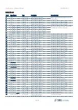
LED
Color code
GNSS LED
OFF: No GNSS available
BLINKING RED:
Unknown positioning mode
RED
: Standalone mode
BLINKING ORANGE
: DGNSS with RTCM data older than 10 seconds
ORANGE
: Stable DGNSS mode with optimal RTCM age
BLINKING GREEN
: Float RTK or PPP solution
GREEN
: Fixed RTK or PPP solution (centimetric accuracy)
INS LED
OFF: Kalman filter is not yet initialized
BLINKING
RED
: Vertical gyro / AHRS mode in alignment phase
RED
: Vertical gyro / AHRS in aligned mode
BLINKING ORANGE
: INS, in alignment phase. INS outputs are not all in "valid state"
ORANGE
: INS is aligned but Position/Velocity/Attitude/Heading are not all in "valid state"
BLINKING GREEN
: INS, in alignment mode. INS outputs are all in "valid state"
GREEN
: INS, is aligned and Position/Velocity/Attitude/Heading are all in "valid state"
A typical design to interface the LEDs is proposed below:
22/48
Figure 3.6: LEDs integration reference design
1
B
E
C
BC846B
VDD_+3V3
R9
1k
R8
1k
1
B
E
C
BC846B
LED1B
LED1A
HSMF-C165
GNSS_LED_A
GNSS_LED_B

