Quanta series
– Hardware Manual
QUANTAHM.1.2
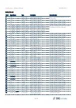
3.4.2.1. Quanta main communication interface
Port A is the main communication interface with the host computer, via sbgECom protocol. It can be used to get
outputs as well as to configure the system.
3.4.2.2. Data output
PORT A, B and C can be configured to output data in a very customized way.
3.4.2.3. RTCM input for RTK operation
RTCM input should be provided on PORT D Rx. In such case, the PORT D Tx will generate a 1Hz GGA message for
optimal network RTK operation.
3.4.2.4. Odometer integration
Odometers should be connected on PORT E Rx (A signal) and PORT E Sync IN (B signal).
3.4.2.5. Third party equipment connection
Remaining serial ports and synchronization pins can be used to connect a third party equipment, either for data
output, or for aiding data input (DVL).
3.4.2.6. Synchronization input and output functions
Sync IN pins can be used to trigger external events and input external PPS information.
Sync Out A and B pins can be configured in the following modes:
●
Main loop divider: This event is activated at the sensor sample time, but its frequency is divided by the
output divider. If the divider is set to 4, pulse output frequency will be 200Hz / 4 = 50Hz.
●
PPS: This simple output is synchronized with each top of UTC seconds. Validity should be checked by parsing
the UTC messages status.
●
Virtual odometer. This output generates a pulse each X meters of travel, depending on user configuration.
20/48

