- 15 -
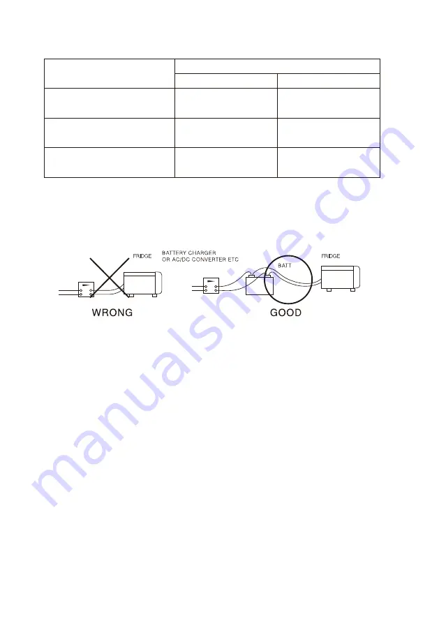
6.2.3 Wiring diagram of dual battery hookup
Battery protection
The wiring diagram shown below is recommended for dual battery
hookup.(See Fig 4)
This fridge is equipped with a battery monitor cutting the
compressor in or out in order to protect the battery. When the
"MODE" button is pressed twice, the LED display will be blinking
the current battery monitor state "OFF" or "LO" or "HI" (default
OFF) .
The "SELECT" button during this mode will display the OFF
⇒
L0
⇒
HI change.
After pre-setting the battery monitor, the LED display
will stop blinking (after a few seconds) , indicating the temperature
has been set (locked) . The value by each setting is shown on the
below table. The battery monitor is not a necessary feature for the
fridge to operate. It may be left in the off position all the time.
Distance between
product and battery
From 6m (19ft.)
to 10m (32ft.)
More than 10m (32ft.)
(Not recommended,too long)
Less than 6m (19ft.)
DC 12 VOLT USE
SWG#16 (AWG#14)
/ 2.1mm
2
or more
DC 24 VOLT USE
Wire Gauge
SWG#18 (AWG#16)
/ 1.25mm
2
or more
SWG#14 (AWG#12)
/ 3.3mm
2
or more
SWG#16 (AWG#14)
/ 2.1mm
2
or more
SWG#12 (AWG#10)
/ 5.3mm
2
or more
SWG#14 (AWG#12)
/ 3.3mm
2
or more
5) Any switches and lead wire for other electrical equipment
should not be shared with the wiring between your fridge and
battery (other equipment sometimes generates high voltage
pulses which may cause defects in the fridge power supply).


