background image

21

Part No. 001300-EN, 07-m01-2022

Ceiling Lift Track Bridge Owner’s Manual

6. MAINTENANCE

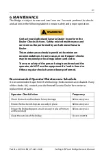
The Bridge is subject to wear and tear from use. You must perform the checks 

and actions in the following tables to ensure safety and proper operation. 

Contact your Authorized Savaria Dealer to perform the 

Dealer Checks/Actions. Safety-related maintenance and 

service must be performed by an Authorized Savaria 

Dealer.
This maintenance schedule provides the minimum 

recommendations. In some cases, more frequent checks 

may be required per local regulations and codes.
To ensure safety of the person being transferred and the 

operator, do NOT use the equipment if a fault is found or 

if these regular checks have not been performed.

Recommended Operator Maintenance Schedule

It is recommended to perform the following checks/actions as indicated. If any 

of the checks fail, contact your Authorized Savaria Dealer for service or 

replacement of parts.

Operator Check/Action

Frequency

Check the track and hardware for any damage

Before every use

Ensure the track end stops are securely in place

Before every use

Ensure the Bridge stoppers are all securely in place (Primary 

and Secondary)

Before every use

Clean the outside of the Bridge

Every 4 months

WARNING

Summary of Contents for Ceiling Lift Track Bridge

Page 1: ...To Be Retained by Owner After Installation by Authorized Savaria Dealer Part No 001 EN Rev m 20 Savaria Ceiling Lift 5SBDL SJEHF OWNER S MANUAL ...

Page 2: ...avoid potential injury due to the use of inadequate parts always use only Savaria replacement parts Regularly scheduled maintenance must be performed on your Bridge by an Authorized Savaria Dealer to ensure safety and proper operation of the Bridge Refer to the Maintenance section in this manual If a serious incident occurs in relation to the device should be reported to the manufacturer or distri...

Page 3: ...dous situation which if not avoided could result in death or serious injury All warning messages feature a standard ISO safety alert symbol followed by the signal word WARNING in capitalized black lettering on a dark yellow background Caution messages indicate a potentially hazardous situation which if not avoided could result in minor injuries All caution messages feature a standard ISO safetyale...

Page 4: ...IPTION 8 Exterior View 8 Device Controls 9 Charger 9 Symbols 10 4 SPECIFICATIONS 13 Dimensions 14 5 USING THE BRIDGE 15 Before Transfer 15 Using the Bridge 16 Manual Operation electrical 19 Manual Operation mechanical 20 6 MAINTENANCE 21 Recommended Operator Maintenance Schedule 21 Recommended Dealer Maintenance Schedule 22 Inspection and Cleaning 23 7 TROUBLESHOOTING 24 8 ELECTROMAGNETIC COMPATIB...

Page 5: ...nnot ensure complete safety for a track Bridge that has exceeded its useful life Wear may cause failure of a part and lead to a patient fall The expected life for other parts such as batteries fuses and cords are dependent upon the proper care and use of the individual items The items mustbemaintained as described intheir accompanying documentationand in the Maintenance section in this manual Usin...

Page 6: ...Do NOT exceed this load Refer to the nameplate tag for the Maximum Load allowed Ensure the track Bridge is installed only with a Savaria ceiling track system and used only with Savaria ceiling lifts The track Bridge and track system must be installed by a trained and Authorized Savaria Dealer Operators must be fully trained before using the lift and Bridge Take care to avoid impact during transfer...

Page 7: ...plenty of water and seek medical attention Inhalation of the contents of the battery can cause respiratory irritation Provide fresh air and seek medical attention For recycling or disposal of batteries follow the rules according to the WEEE directive Waste of Electronic and Electrical Equipment as well as all local laws and regulations If you do not follow these rules the battery may explode leak ...

Page 8: ...hat the Bridge will only work with devices equipped with a magnetic block as shown below For magnetic block installation and kit assembly refer to the Track Installation section in the Track Installation Guide 001076 Figure 2 ON OFF switch Magnetic block installed on portable trolley when used with portable lift Magnetic block installed on fixed lift Kit provided with the Bridge ...

Page 9: ... charging system 2 Light OFF Device is OFF 2 Green Solid Device is powered ON and ready 2 Green Flashing Device battery is low Note An audiblebeepis emittedapproximatelyevery minute in addition to the flashing indicator 2 Red Solid Device malfunction jammed time out etc 3 Light OFF Device is ready for use 3 Amber Solid Inspection required Call Authorized Savaria Dealer LED Description 1 When ON fu...

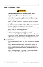
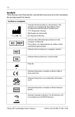
Page 10: ... the year MM Represents the month DD Represents the day Indicates the authorized representative in the European Community This symbol is accompanied by the address of the authorized representative Indicates the manufacturer s catalogue number Indicates the manufacturer s serial number Keep dry Indicates the product complies with the medical device directive Indicates the product was certified by t...

Page 11: ...nst electrical shocks MAX LOAD Refers to the greatest permissible load that can be applied to the product IPX1X2 Ingress Protection X1 Protection level against ingress of solid particles X2 Protection level against ingress of liquids Unique Device Identification UDI symbol required by the FDA Indicates the product is a medical device according to EU Medical Device Regulation 2017 745 ...

Page 12: ...vice can be safely exposed Indicates the range of humidity to which the medical device can be safely exposed Indicates the range of atmospheric pressure to which the medical device can be safely exposed Symbols on device Indicates that the device is on charge or charged Indicates the power status Indicates thatmaintenance is recommended on the device ...

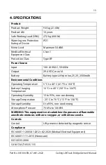
Page 13: ...V 2500mAh Environmental Conditions Operating Temperature 5 C to 40 C 41 F to 104 F Battery Charging Temperature 10 C to 40 C 50 F to 104 F Operating Humidity 15 to 93 non condensing Storage Temperature 25 C to 70 C 13 F to 158 F Storage Humidity 0 to 93 non condensing Atmospheric Pressure 70 kPa to 106 kPA WARNING This equipment is not suitablein the presenceof flammable anesthetic mixtures with a...

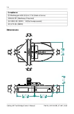
Page 14: ...Lift Track Bridge Owner s Manual Part No 001300 EN 07 m01 2022 Dimensions Compliance CE Marking per MDR EU 2017 745 Medical Device 2006 42 EC Machinery Directive 2015 863 EU ROHS 100 of components 2012 19 EU WEEE ...

Page 15: ...ose when the device is disengaged Ensure these stoppers are in correct position Any track extremities other than the extremities blocked by theBridge shall have end stops securely in place as shown below Inform the person to be transferred what you are about to do The beep and the locking process can cause stress if the process is unknown Figure 5 TRACK END STOP ...

Page 16: ...Bridge 1 Move the ceiling lift inside the Bridge Figure 6 2 Move the mobile Bridge Primary in front of the fixed Bridge Secondary You will hear a beep confirming that the Bridge is positioned correctly Figure 7 3 After less than two seconds the Bridge will automatically become engaged ...

Page 17: ...eiling Lift Track Bridge Owner s Manual 4 Move the lift across the fixed Bridge Secondary and into the track The bridges will remain locked together until the lift returns and crosses the bridge to go back into the mobile track Figure 8 ...

Page 18: ...18 Ceiling Lift Track Bridge Owner s Manual Part No 001300 EN 07 m01 2022 5 To disengage the Bridge move the lift across both Bridges for it to automatically disconnect Figure 9 Figure 10 ...

Page 19: ...l The handset may spring return and cause injuries NEVER leave a person unattended during a transfer to prevent the person from falling and sustaining possible injuries Manual Operation electrical In the unlikely event of Bridge failure you can use the bypass button to manually operate the Bridge Figure 11 CAUTION WARNING ...

Page 20: ...eiling Lift Track Bridge Owner s Manual Part No 001300 EN 07 m01 2022 Manual Operation mechanical In the unlikely event of Bridge failure you can use a 4mm Allen Key to manually operate the Bridge Figure 12 ...

Page 21: ...ed per local regulations and codes To ensure safety of the person being transferred and the operator do NOT use the equipment if a fault is found or if these regular checks have not been performed Recommended Operator Maintenance Schedule It is recommended to perform the following checks actions as indicated If any of the checks fail contact your Authorized Savaria Dealer for service or replacemen...

Page 22: ...m falling or objects from falling that may cause injuries to the person the operator or other persons always reinstall the track end stops if they were removed for servicing Note that the recommended tightening torque for the track end stop is 20 N m 15 lb ft Figure 13 shows the track end stop Figure 13 Dealer Check Action Frequency Check all inside hardware to ensure it is properly tightened Ever...

Page 23: ...e cloth or wipe to ensure thorough cleaning of the entire surface Do not splash drench or immerse the unit in water as the unit could malfunction causing injuries to occur Do NOT open the Bridge cover Only an Authorized Savaria Dealer is qualified to open it Modifications made to the device by someone other than a qualified technician may cause serious injury To ensure a better rolling surface for...

Page 24: ...the problem persists and the Bridge still does not operate contact your Authorized Savaria Dealer for service Bridge doesn t beep or engage Make sure the power switch is in the ON position Ensure the charger is plugged into the power outlet and connected to the CCR strip Verify also that the CCR brushes are plugged into the Bridge Bridge emits a beep every minute Verify the charger is properly plu...

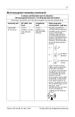
Page 25: ... cables and external antennas should be used no closer than 30 cm 12 inches to any part of the Bridge including cables specified by the manufacturer Otherwise degradation of the performance of this equipment could result Guidance and Manufacturer s Declaration Electromagnetic Emissions For All Equipment and Systems The Bridge is intended for use in the electromagnetic environment specified below E...

Page 26: ...ir 8 kV contact 15 kV air Floors should be wood concrete or ceramic tile If floors are covered with synthetic material the relative humidity should be at least 30 Surge IEC 61000 4 5 1 kV differential mode 2 kV for common mode 1 kV differential mode 2 kV for common mode Mains power quality should be that of a typical commercial or hospital environment Power frequency 50 60 Hz magnetic field IEC 61...

Page 27: ...ations equipment should be used no closer to any part of the Bridge including cables than the recommended separation distance calculated from the equation applicable to the frequency of the transmitter Recommended separation distance where P is the maximum output power rating of the transmitter in watts W according to the transmitter manufacturer and d is the recommended separation distance in met...

Page 28: ...hat are not Life Supporting Recommended separation distances between portable and mobile RF communications equipment and the Bridge The Bridge is intended for use in electromagnetic environments in which radiated RF disturbances are controlled The customer or the user of the Bridge can help prevent electromagnetic interference by maintaining a minimum distance between portable and mobile RF commun...

Page 29: ...THIS PAGE WAS LEFT INTENTIONALLY BLANK ...

Page 30: ...THIS PAGE WAS LEFT INTENTIONALLY BLANK ...

Page 31: ...THIS PAGE WAS LEFT INTENTIONALLY BLANK ...

Page 32: ...rd Lifts Inc 2 Walker Drive Brampton Ontario L6T 5E1 Canada www savaria com For service or questions about this product please contact your installing dealer DEALER NAME _________________________________________________ DEALER PHONE _________________________________________________ Authorized Savaria Dealer ...

Reviews: