background image

Savant Standalone Energy Monitor Deployment Guide

Copyright 2020 Savant Systems, Inc

009-1928-01  |  200828

19     of     24

5.  Web User Interface (Web UI SEM-2015 Only)

The SEM-2015 includes a web-based user interface (web UI) with additional programming and configuration options, some of which are required for 

successful deployment.  To access and configure the Web UI, follow the steps listed below from the Savant Development Environment (SDE/MacBook) 

while connected to the same local network as the SEM-2015. 

1. 

Locate the IP address for the SEM-2015 via System Monitor, 

or using any network scanning utility.

2.  Open a web browser and enter the device IP into the address bar.

 IMPORTANT!


When first connecting to the SEM-2015, the user is required 

to set a password.


If the password needs to be reset, follow the Device Reset 

instructions found in the device’s Quick Reference Guide.

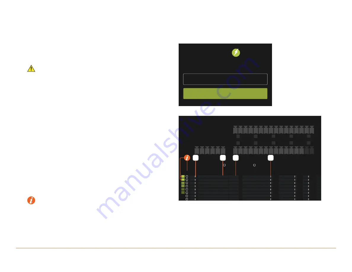
3.  Enter device password (or set password if accessing for first time), 

then select 

LOGIN

 to continue. 


4.  Select the Voltage Transformer Connection.
5.  Enter a label for the current transformer.
6.  Enter the Current rating of the current transformer.
7.  Select the circuits Classification.
8.  Repeat steps 4 though 7 for each current transformer is use.
9.  Click 

Deploy Config

.

 HELPFUL INFO

:


Inv: This column stands for invert.  If a current transformer reports a negative current value (potentially wired backward), check this option to 

multiply reported value by -1, making it positive.


Linked Phases

: Combines the readings from multiple current transformers when a circuit utilizes more than 1 phase.  

Auto-Link

: Links circuits with matching labels.  To disable this feature, check the Disable Auto-Link option above the table.. 

Link Highlighting

: Shows matching green squares on linked current transformers. This feature can be disabled by checking the box labeled Disable 

Link Highlighting above the table.

PASSWORD

LOGIN

SYSTEM MONITOR

RACEPOINT

CT CONNECTIONS

VT CONNECTIONS

+A - +B - +C -

+ 1 - + 2 - + 3 - + 4 - + 5 - + 6 - + 7 - + 8 -

+ 9 - +10 - +11 - +12 - +13 - +14 - +15 - N/A

Disable Auto-Link

Disable Link Highlighting

ID Inv

VT

Conn.

Label

Current

Classification

Group

Linked Phases

250
250

150
150

50
50
20
20

Main Feed

Main Feed

HVAC
HVAC

Dryer
Dryer

Refrigerator

Stove

Consumption
Consumption
Consumption
Consumption
Consumption
Consumption
Consumption
Consumption
Consumption

---
---
---
---
---
---

---

---
---

2
1
4
3
6
5

---

---
---

---
---
---
---
---
---

---

---
---

A
B
A
B
A
B

A

A
B

1

2
3
4
5
6
7
8

7

6

5

4

Summary of Contents for SmartEnergy SEM-1024

Page 1: ...Monitors are connected to a home s existing electrical panel using clip on current transformers and to the Savant Host via the local network They allow the user to monitor all aspects of energy usage...

Page 2: ...Three Phase Consumption Only 6 2 3 Single Phase with Power Generation 7 3 Installation 8 3 1 Flat Surface 8 SEM 2015 8 SEM 1024 8 3 2 Din Rail 9 3 3 Voltage Transformers 10 3 4 Current Transformers 11...

Page 3: ...device 9 If the provided plug does not fit the desired outlet contact a licensed electrician to replace the obsolete outlet 10 Protect any power cord from being walked on pinched strained or otherwise...

Page 4: ...page can be used as a checklist to mark progress as steps are completed Review product specifications and connection details See the device s Quick Reference Guide on the Savant Customer Community Ins...

Page 5: ...eployment Guide Copyright 2020 Savant Systems Inc 009 1928 01 200828 5 of 24 2 System Diagrams 2 1 Single Phase Consumption Only Typical 200 Amp Service Power from Utility Current Transformers Voltage...

Page 6: ...ant Standalone Energy Monitor Deployment Guide Copyright 2020 Savant Systems Inc 009 1928 01 200828 6 of 24 2 2 Three Phase Consumption Only Current Transformers Voltage Transformers Main Branch Monit...

Page 7: ...ds true for Wind Geothermal or Auxiliary Generators Power from Utility Current Transformers Solar Voltage Transformers Main Branch Monitors Inverter s TIP The diagram above shows one example of how to...

Page 8: ...ilable wall anchors can be used SEM 1024 Mounts to a wall or similar surface using the included chassis mounted side brackets and supplied M3 x 8mm flat head screws Mount chassis in a place that is dr...

Page 9: ...ed universal din rail clip To install using a Din Rail do the following 1 Remove the screws holding the mounting plate on the bottom of the unit 1 2 Remove the mounting plate 3 Align the Universal Din...

Page 10: ...uit is run into the box 1 Switch the circuit breaker to the circuit that the SEM VT01 is being added to 2 Using diagram to the right make high voltage connections 3 Screw the SEM VT01 into the electri...

Page 11: ...e proper polarity install the 20 and 50A current transformers with arrows pointing in the direction of current flow towards the load C Route the wire through a cable clamp on the side of the panel and...

Page 12: ...ct the Energy Monitor and drag into a Global Zone 4 Name the device 5 Place the Energy Monitor in the Layout window 6 Select the Energy Monitor 7 Open Inspector 8 Enter UID Components All Control Type...

Page 13: ...s Energy Monitor 2 Click the Add for SEM2015 Add for SEM1024 2 3 3 Select the Energy Monitor to be used 4 Double click on the Circuit Description Enabled Circuit Description Classification Group Image...

Page 14: ...n Group Image Monitoring Device Channel Size Voltage Source Parent Circuit Control Savant Zone Group Image Production Type Main Power None Feed SEM2015 1 None Choose Utiliy Ro Phase 1 Channel 250 A Vo...

Page 15: ...e house From an open Blueprint configuration do the following 1 Go to Tools Settings Energy Monitor 2 Click the Add for SEM2015 Add for SEM1024 2 3 3 Select the Energy Monitor to be used 4 Double clic...

Page 16: ...n Family Room Room SEM2015 10 None Choose Family R Phase 1 Channel Consumption 9 Phase 2 Channel Consumption Only Main Feed Key Loads This example shows the main power feed and key loads being monitor...

Page 17: ...Consumption Consumption Production Family Room Room SEM2015 10 None Choose Family R Phase 1 Channel Consumption 9 Phase 2 Channel Solar Auxiliary Generator The example below shows a completed configu...

Page 18: ...Phase 1 Channel Dishwasher Appliances SEM2015 01 6 None Choose Kitchen Phase 1 Channel A C hvac SEM2015 01 7 None Choose Utiliy Ro Phase 1 Channel Work Shop None SEM2015 02 1 None Choose Work Sh Phase...

Page 19: ...he Current rating of the current transformer 7 Select the circuits Classification 8 Repeat steps 4 though 7 for each current transformer is use 9 Click Deploy Config HELPFUL INFO Inv This column stand...

Page 20: ...al Voltage sensor for use in conjunction with Savant Energy Monitors SEM 020A5 SEM 020A5 is a 5 pack of 20 Amp split core clip on current transformers SEM 050A5 SEM 050A5 is a 5 pack of 50 Amp split c...

Page 21: ...tems Inc 009 1928 01 200828 21 of 24 SKU Description Image SEM 250A1 SEM 250A1 is a 250 Amp split core clip on current transformer SEM 400A1 SEM 400A1 is a 400 Amp split core clip on current transform...

Page 22: ...he end user accesses their monitoring info within the Savant UI Select a predefined group same list or select the text field to enter a custom group name Configured groups form the top level navigatio...

Page 23: ...fication Options include Generator Solar or Battery Clicking this box will do the following If a circuit level row is selected or there is no selection a new circuit will be added If a phase channel i...

Page 24: ...l rights reserved Savant Savant App TrueImage Savant Host Now You Can RacePoint Blueprint Single App Home TrueCommand TrueControl and the Savant logo are trademarks of Savant Systems Inc AirPlay Apple...

Reviews: