background image

Overview of models

2 - 23

7000928003  R4

Sauter Components

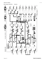
Block diagram RDT 300

Model 3

+

-

X

w

1

X

n

1

N

eu

tr

a

lz

o

n

e

1

X

w

r

X

w

1

y1

X

i1

P

I

C

on

tr

ol

le

r

1

yc

1

X

p

1

T

n1

X

p

1

/

X

i2

y1

P

I3

P

I1

dX

i4

bX

i4

bX

i4

cX

i4

T

F

4

(J

u

m

p

e

r)

x

xi

d

X

i3

b

X

i3

b

X

i3

cX

i3

T

F

3

(J

u

m

p

e

r)

x

xi

d

X

i2

b

X

i2

b

X

i2

cX

i2

T

F

2

(J

u

m

p

e

r)

X

i1

d

X

i1

b

X

i1

b

X

i1

cX

i1

T

F

1

(J

u

m

p

e

r)

x

xi

x

xi

X

i5

cX

i5

T

F

5

X

i6

cX

i6

T

F

6

x

xi

X

i2

X

i3

X

i4

D

e

w

po

in

t

ca

lc

u

la

tio

n

f=

(H

%

+

T

)

°C

T

P

y3

y

yc

L

Y

/

Y

o

1

0

V

L

Y

.

R

el

.1

y2

y

yc

L

Y

/

Y

o

1

0

V

0

1

0

0

%

L

Y

.

y1

y

yc

L

Y

/

Y

o

1

0

V

0

1

0

0

%

L

Y

.

R

1

P

U

P

(I

)

C

o

nt

ro

lle

r

lim

ite

r

4

yc

4

X

p4

T

n

4

X

p4

/

M

a

x

R

el

.2

R

2

P

U

R

el

.3

R

3

P

U

R

el

.4

R

4

P

U

R

el

.5

R

5

P

U

R

el

.6

R

6

P

U

1

00

%

X

s

sw

itc

ho

ve

r

F

lo

w

te

m

p

.

fo

r

h

ea

tin

g

O

ut

do

or

te

m

p

.

H

um

id

ity

cX

s3

H

e

at

in

g

cu

rv

e

T

e

m

pe

ra

tu

re

X

s3

/4

cX

s1

X

s1

/2

X

s(

T

P

)

L

1

L

1d

H

L

1

(x

ts

w

itc

h

ov

e

r)

P

um

p

H

e

at

in

g/

co

o

lin

g

C

h

an

ge

ov

e

r

(C

/O

)

H

e

at

in

g/

co

ol

in

g

(M

in

)

°C

T

P

t

cX

s4

T

P

+

X

w

4

-

+

H

ea

tin

g

D

u

al

p

ip

e

in

st

al

la

tio

n

C

/O

X

X

n

2

N

e

u

tr

a

lz

o

ne

2

X

w

2

-

X

w

2

P

I

C

on

tr

ol

le

r

2

(m

ai

n

co

n

t.)

X

p

2

T

n2

X

p

2

/

t

C

oo

lin

g

+

X

s

sw

itc

ho

ve

r

X

s

sw

itc

ho

ve

r

O

f

re

fe

re

n

ce

ro

o

m

yc

2

C

om

m

an

d

-

au

x.

co

n

tr

ol

le

r

yc

rX

sc

rX

sc

cX

s

0

1

0

0%

P

I

C

on

tr

ol

le

r

3

(a

ux

il.

co

n

tr

.)

X

p

3

T

n

3

X

p

3

/

t

C

oo

lin

g

yc

3

X

w

3

+

G

ro

un

d

te

m

p

.

yc

2

yc

3

X

i3

X

i6

P

I2

H

ea

tin

g

C

oo

lin

g

(c

as

ca

d

e)

O

pt

io

n:

sh

ift

yc

1

yc

4

B

A

X

i.

y.

P

I5

e.

g.

de

hu

m

id

ifi

ca

tio

n

x

xi

X

i.

P

I

C

o

nt

ro

lle

r

5

yc

5

X

p

5

T

n

5

X

p

5

/

t

yc

5

+

-

X

w

5

X

s5

L

2

L

2

d

H

L

2

L4

L4

d

H

L

4

L

3

L

3

d

H

L3

C

h

an

ge

ov

er

sw

itc

ho

ve

r

O

p

tio

n:

a

ct

iv

er

de

w

p

o

in

ti

n

p

ut

D

ry

flo

o

rin

g

fu

nc

tio

n

H

ea

tin

g

+

co

ol

in

g

H

ea

tin

g

o

nl

y

C

oo

lin

g

on

ly

O

ff

w

ith

fr

o

st

pr

ot

e

ct

io

n

O

pe

ra

tin

g

m

od

e

(B

A

):

S

w

itc

ho

ve

r

vi

a

ke

yp

a

d

o

r

re

m

o

te

co

n

tr

o

l

X

i3

<

re

le

as

e

va

lu

e

O

ut

do

or

te

m

p

.

X

i3

/

X

i3

X

i3

>

(r

e

le

as

e

va

lu

e

+

d

iff

e

re

n

tia

lv

a

lu

e

)

=

h

e

at

in

g

m

o

d

e

B

A

=

co

o

li

n

g

m

o

d

e

B

A

M

in

im

u

m

o

p

er

a

tin

g

p

er

io

d

L

o

g

ic

C

h

a

n

ge

o

ve

r

sw

itc

h

o

ve

r

C

/O

X

n

4

N

e

u

tr

a

lz

o

n

e

4

X

w

r

X

w

4

C

o

m

m

a

n

d

m

o

du

le

2

xi

.

2

F

P

2

F

1

X

s

W

s2

A

cX

sh

B

0

9

3

8

6

C

o

m

m

a

n

d

m

o

du

le

1

xi

.

1

F

P

1F

1

X

s

W

s1

B

Y

C

O

A

B

X

s

sw

itc

ho

ve

r

T

im

e

ch

a

nn

el

F

le

x

o

tr

o

n

30

0

F

lo

w

te

m

p

.

fo

r

co

ol

in

g

=

Li

nk

ca

n

b

e

ch

an

ge

d

S

ub

je

ct

to

ch

an

ge

s!

V

a

lv

e

a

nt

i-

ja

m

m

in

g

p

ro

te

ct

io

n

V

a

lv

e

a

nt

i-

ja

m

m

in

g

p

ro

te

ct

io

n

V

a

lv

e

a

nt

i-

ja

m

m

in

g

p

ro

te

ct

io

n

Summary of Contents for RDT 300 F001

Page 1: ...7000928003 R4 Sauter Components Flow temperature controller for heating cooling User s Manual part 2 RDT 300 F001 7000928003 R4...

Page 2: ...7000928003 R4 Sauter Components...

Page 3: ...User keys with function keys Setpoint Actual value Control deviation Positioning signal Input Limit Date and time Forwards Backwards and minus sign Flap holds instructions Memory option Mode switch M...

Page 4: ...7000928003 R4 Sauter Components...

Page 5: ...00 24 Block diagram RDT 300 Model 4 25 Description of functions RDT 300 26 Block diagram RDT 300 Model 5 27 Description of functions RDT 300 28 Block diagram RDT 300 Model 6 29 Description of paramete...

Page 6: ...e constant 40 Tn Integral action time reset time standardised term 40 Ver Version 40 W Shift W 40 Xi Actual value standardised term 41 Xm Balancing of measured value Xi 41 Xn X neutral 41 Xp Proportio...

Page 7: ...nfigure and if necessary adjust the measured value inputs set the control actions and modes of action configure the control outputs In the parameterising procedure described below the grey fields cont...

Page 8: ...2 4 Service 7000928003 R4 Sauter Components...

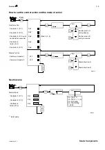
Page 9: ...PI 1 heating if activated Controller PI 5 Source Dry flooring function Activation Remote control Activation Changeover Switchover criterion 1W 2W 3H 5r ETF RC MCO Input Inactive Source Xi1 6 Xi3 aver...

Page 10: ...o factory setting Enter Code Cl OK Yes No Copies the parameters from the controller into Memory Restart Ini Reinitialisation Copies parameters from memory into Controller Software version Device type...

Page 11: ...1000 0 10V 2 10V 0 20mA 4 20 mA 0 1V Active dewpoint input Xi4 only I cXi Unit of measurement can only be changed if input is active dXi1 dXi2 dXi3 dXi4 Input C r H g kg kJ kg dXi Free unit of measur...

Page 12: ...t of measure ment is not displayed Xm1 Xm2 Xm3 Xm4 Xm5 Xm6 Xm Cl Input Measured value TF Cl Input 0 255s OF Cl Input Value measured value Xm display Xi B09375a 2 s 2 s 2 s 2 s 2 s 2 s How to set the s...

Page 13: ...de of action Command module 1 Command module 2 1 Xp1 Xp2 Xp3 Xp4 Xp5 W1 W2 PAR 6 Input Mode of action A Mode of action B I I W Input Control action A acting directly Control action B acting in reverse...

Page 14: ...deviations Calculated positioning signals y3 Xi3 I I rY3 rY3 Start of range 0V End of range 10V 25 0 C rY3 Cl Input 30 0 150 0 C 0 0 100 0 r H 0 0 20 0 g kg 0 0 100 0 kJ kg 4999 4999 41 0 C 0 YM Inpu...

Page 15: ...LY2 LY3 0 0 100 0 Input Cl RP1 RP2 RP3 RP4 RP5 RP6 YP1 YP2 YP3 Blocking protection Relay 1 Relay 2 Relay 3 Relay 4 Relay 5 Relay 6 Positioning outputs Positioning signal Y1 Positioning signal Y2 Posi...

Page 16: ...1 Ld1 HL1 L2 Ld2 HL2 L3 Ld3 HL3 L4 Ld4 HL4 c O c Od1 c Od2 HY Co t od nr ALErt Input Xi1 Xi2 Xi3 Xi4 Xi5 Xi6 nXi3 Xw1 Xw2 Y1 Y2 Y3 Yc1 Yc2 Yc3 Yc4 Yc5 Co OFF I I HL_ Cl Input 0 0 150 0 C 0 0 100 0 r H...

Page 17: ...Service 2 13 7000928003 R4 Sauter Components Clock function 0 Clock Correct running accuracy 1 Adj Adj Cl Input 199 199 s Enter deviation in seconds month B09382 1 Enter code...

Page 18: ...2 14 Service 7000928003 R4 Sauter Components...

Page 19: ...Overview of models 2 15 7000928003 R4 Sauter Components Overview of models...

Page 20: ...g is controlled by outdoor temperature based on heating curve flow temperature for cooling with shift operating mode changeover is internal or via external system remote control off mode with frost pr...

Page 21: ...PI Controller 2 yc2 Xp2 Tn2 Xp2 Xs TP xt switchover Pump Heating cooling Changeover C O Heating cooling Min C TP t t cXs4 TP Xw4 L2 L2d HL2 Link can be changed Heating Cooling Time channel Dual pipe i...

Page 22: ...door temperature averaged and damped can be switched off flow temperature for heating controlled by outdoor temperature based on heating curve operating mode changeover internal or by external system...

Page 23: ...2 R2PU Rel 3 R3PU Rel 4 R4PU Rel 5 R5PU Rel 6 R6PU 100 Xs switchover Flow temp for heating Outdoor temp cXs1 Xs1 2 xt switchover Pump Heating Heating t L2 L2d HL2 Heating Time channel Dual pipe insta...

Page 24: ...e g for dehumidification flow temperature for cooling with shift operating mode changeover internal or via external system remote control valve anti jamming function pump blocking protection active de...

Page 25: ...6PU 100 Xs switchover Flow temp for cooling Outdoor temp Humidity cXs3 Xw2 Temperature Xs3 4 PI Controller 2 yc2 Xp2 Tn2 Xp2 Xs TP xt switchover Pump Cooling Cooling Min C TP t cXs4 TP Xw4 L2 L2d HL2...

Page 26: ...led by outdoor temperature based on heating curve flow temperature for cooling with ground temperature input corresponds to a cascade control operating mode changeover internal or via external system...

Page 27: ...oller 2 main cont Xp2 Tn2 Xp2 t Cooling Xs switchover Xs switchover Of reference room yc2 Command aux controller yc rXsc rXsc cXs 0 100 PI Controller 3 auxil contr Xp3 Tn3 Xp3 t Cooling yc3 Xw3 Ground...

Page 28: ...n flow temperature for cooling with ground temperature input corresponds to cascade control operating mode changeover internal or via external system remote control valve anti jamming function pump bl...

Page 29: ...3 4 Xs TP L1 L1d HL1 xt switchover Pump cooling Cooling Min C TP cXs4 TP Xw4 Time channel Dual pipe installation X Xn2 Neutral zone 2 Xw2 Xw2 PI Controller 2 main contr Xp2 Tn2 Xp2 t Cooling Xs switch...

Page 30: ...ature based on heating curve flow temperature for cooling with shift operating mode changeover internal or via external system remote control off mode with frost protection flooring function as per DI...

Page 31: ...ump Heating Changeover C O Heating Min C TP t t cXs4 TP Xw4 L2 L2d HL2 Heating Cooling Time channel Four pipe installation L4 L4d HL4 Xs switchover Xs switchover Changeover switchover Of reference roo...

Page 32: ...eating curve flow temperature for cooling with ground temperature input corresponds to cascade control operating mode changeover internal or via external system remote control off mode with frost prot...

Page 33: ...ler 2 main contr Xp2 Tn2 Xp2 t Cooling Xs switchover Xs switchover Of reference room yc2 Command aux contr yc rXsc rXsc cXs 0 100 PI Controller 3 aux contr Xp3 Tn3 Xp3 t Cooling yc3 Xw3 Ground temp yc...

Page 34: ...2 30 Overview of models 7000928003 R4 Sauter Components...

Page 35: ...Description of parameters 2 31 7000928003 R4 Sauter Components Description of parameters...

Page 36: ...2 32 Description of parameters 7000928003 R4 Sauter Components...

Page 37: ...OFF to deacti vate the shift module On activation the shift acts on controller PI 1 heating or the heating curve can also be assigned as an alternative 3H Heating curve input Access Service level Sour...

Page 38: ...vel can also be prevented by sealing the mode switch cXi config Xi Access Service level Settings for the type of sensor connected In addition the jumpers should be inserted at the rear of the unit Pos...

Page 39: ...cess Service level Activates the dry flooring function indicated by a flashing symbol in automatic operation When the ETF has been started the controller initially regulates a flow temperature that is...

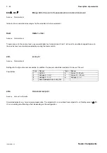
Page 40: ...isation Access Service level Resets the controller s EEPROM parameter memory to the default values Default values are shown with a grey background in the operating instructions L Limit Access Service...

Page 41: ...as follow up for triggering heating pumps LY Limit Y Access Service level Value and mode of action of the Y limitation This limitation can be set for positioning signals only and it only works in auto...

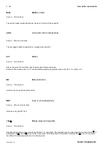
Page 42: ...mple Measured value 20 0 C preferred display balancing of measured value 20 5 C offset 0 5 RC Remote Control Access Service level Activates the connected remote control RDT Type of unit designation Ac...

Page 43: ...rt of the range for the measurement amplifier with 0 Volt output e g 20 C If you enter rY3 rY3 for example a P controller can be configured with mode of action B WS shift W Access Manual Amount of shi...

Page 44: ...ge The delay causes an additional phase shift in the control loop which can lead to hunting This function is intended for example for use in room pressure control for arresting pressure surges Do not...

Page 45: ...l Sets the neutral zone for the relevant control module The controller s output is frozen within this zone If Xw stays within the amount of Xn 2 the control deviation is considered to be 0 The functio...

Page 46: ...ion standardised term Access Manual automatic Difference between controlled variable Xi and setpoint Xs Y Positioning signal standardised term Access Manual automatic Controller output voltage signal...

Page 47: ...of either 0 10 V or 2 10 V YM Ymin selection Ymax selection Access Service level Positioning signals Yc2 and Yc3 are only available if they are linked by selection Maximum selection can also be achie...

Page 48: ...2 44 Description of parameters 7000928003 R4 Sauter Components...

Page 49: ...List of parameters 2 45 7000928003 R4 Sauter Components List of parameters...

Page 50: ...2 46 List of parameters 7000928003 R4 Sauter Components...

Page 51: ...SERV i i i i i i i Input 1 Flow temperature heating Xi1 Actual value Depends on transmitter and unit of meas m t A H Xi i i i i i i i cXi1 Type of transmitter Note code plug position 1 Ni 1000 2 0 10...

Page 52: ...cXi2 Type of transmitter Note code plug position 1 Ni 1000 2 0 10 V 3 2 10 V 4 0 20 mA 5 4 20 mA 6 0 1 V S Xi 1 i i i i i i i dXi2 Unit of measurement C r h g kg kJ kg No unit of measure ment S Xi C i...

Page 53: ...20 mA 6 0 1 V S Xi 1 i i i i i i i dXi3 Unit of measurement C r h g kg kJ kg No unit of measure ment S Xi C i i i i i i i bXi3 End of range Depends on transmitter and unit of meas m t S Xi 150 C i i...

Page 54: ...meas m t S Xi 100 i i i i i i i bXi4 Start of range Depends on transmitter and unit of meas m t S Xi 0 0 i i i i i i i Xm4 Calibration S Xi i i i i i i i OF4 Offset value S Xi i i i i i i i TF4 Filte...

Page 55: ...1F1 End of shift H PAR 22 0 C i i i i i i 1 Ws Amount of shift H PAR 3 0 C i i i i i i Command module 2 Heating alternative to heating curve target for controller 1 2W Source if active target is fixed...

Page 56: ...s 45 0 C i i i i i rXs1 Minimum value Xs1 2 30 0 150 0 C S Xs 10 0 C i i i i i cXs1 Flow temp setpoint heating A H Xs i i i i i Soll Calculated values as per heating curve A H Xs i i i i i Controller...

Page 57: ...PAR i i i i i cXs4 Calculated dewpoint C TP A H Xs i i i i i Xp4 Proportional band 0 1 250 C H PAR 10 0 C i i i i i Tn4 Integral action time 0 9999 s H PAR 180 s i i i i i TPI Dewpoint interval 5 5 C...

Page 58: ...ning signal A H Y i i i i i i i YP2 Valve anti jamming function On Off S Y On i i i i i i i Positioning signal Y3 LY3 Limitation Limitation value 0 0 100 0 S Y 0 0 i i i i i i i Y3 Source measurement...

Page 59: ...i i i T0 Time channel Auto On Off A H Y Auto i i i i i i i Rel1 Relay 1 On Off A H Y In Manual OFF i i i i i i i Rel2 Relay 2 On Off A H Y In Manual OFF i i i i i i i Rel3 Relay 3 On Off A H Y In Manu...

Page 60: ...Lv2 Delay time 0 9999 s A H L 0 s i i LN2 Follow up time 0 9999 s A H L 180 s i i Limit value 3 L3 Assignment of source S L Xi3 c o c o Ld3 Target relay Rel 1 6 S L Rel 6 i i L3 Limit value see Xs A...

Page 61: ...HYCo x Hysteresis S L 1 0 C i i i i Co x Switching point A H L 23 C i i i i Cov x Delay time A H L 2 s i i i i Con x Follow up time A H L 0 s i i i i FH x Release value heating H PAR 22 C i i i i HK...

Page 62: ...i i i i i Clock functions Xs_ Setpoint change over for contr 1 Xs1 2 Day of week time H PRO Xs1 0 06 00 Xs2 0 22 00 i i i i i i i Xs_ Setpoint change over for contr 2 Xs3 4 Day of week time H PRO Xs3...

Page 63: ...230V 5 2 A 230 L N xi xi xi Ni1000 0 2 10V Ri 100k 0 1V Ri 500k xi 0 4 20mA Ri 50 Input X1 X3 Input X4 xi 0 10V Ri 100k A09432d 21 22 23 24 A B 15V RDB 300 21 22 23 24 xi xi xi Ni1000 0 2 10V Ri 100k...

Page 64: ...2 60 List of parameters Sauter Components Printed in Switzerland Right of amendment reserved N B A comma between cardinal numbers denotes a decimal point Fr Sauter AG CH 4016 Basle 7000928003 R4...

Reviews: