background image

5

  Replacement

59

S84-ex/S86-ex Service Manual

5.2 Replacing the Print Head

If the print head becomes damaged or worn, it can be easily removed and replaced without having to 
make critical adjustments.

WARNING

• Do not touch the power switch, connect or disconnect the power cord while your hands are wet. Doing so 

could cause an electric shock.

• Disconnect the power cord from the AC outlet before you replace the print head.
• Wear gloves before replacing the print head, to prevent damage to the print head.

5.2.1

Replacing the Print Head (without the Optional UHF RFID 
Antenna Installed)

1

Make sure that the printer is in power off 
mode, then disconnect the power cord 
from the AC outlet.

2

Open the 

top cover

 of the printer.

CAUTION

Open the top cover fully to prevent accidental drop of 
the cover.

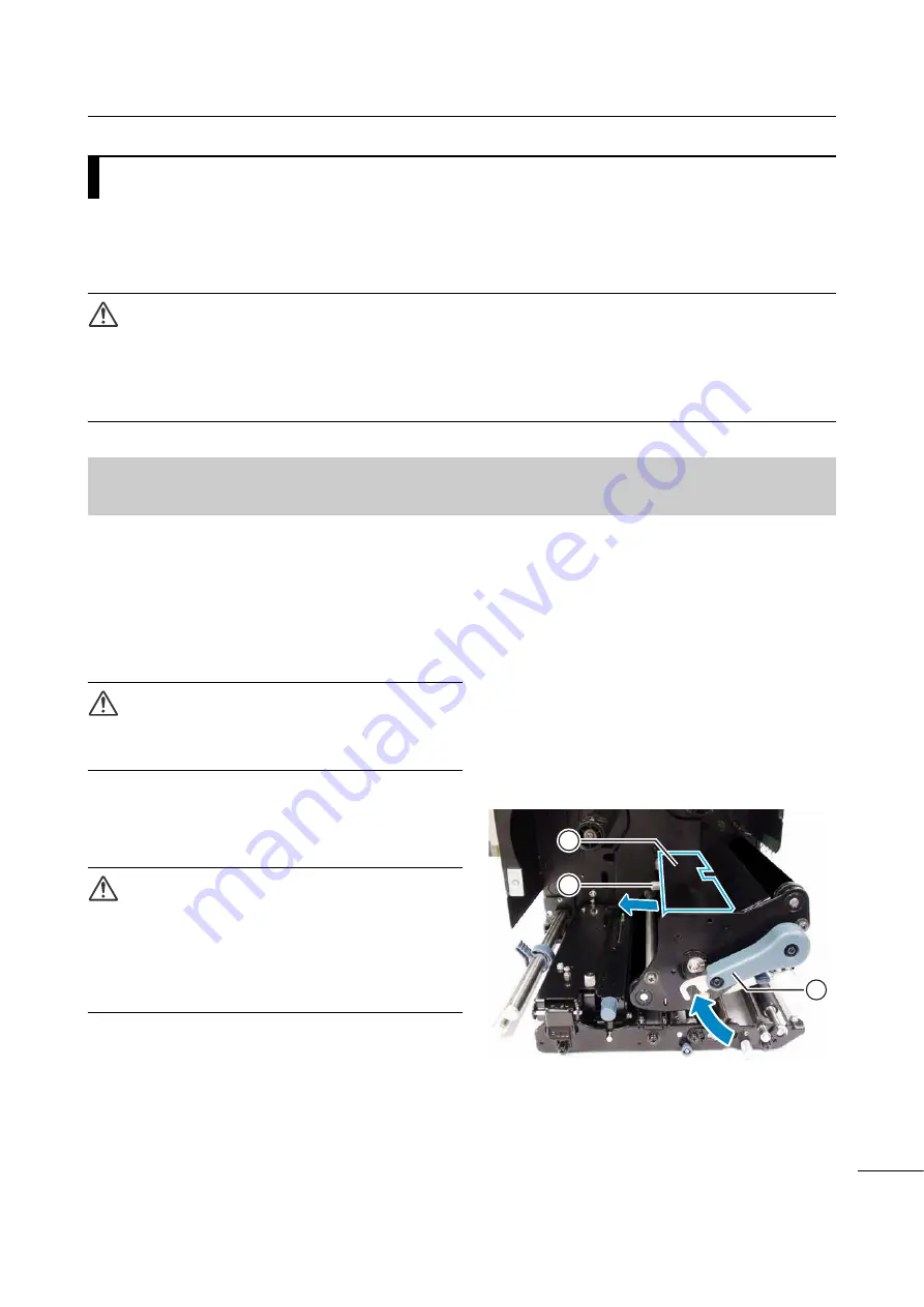
3

Turn the 

head lock lever


 clockwise to 

unlock the 

print head

.

CAUTION

• The print head and its surroundings are hot after 

printing. Be careful not to touch it, to avoid being 
burned.

• Touching the edge of the print head with your bare 

hand could cause injury.

4

Remove the 

thumbscrew


 attached to 

the 

cover


 on top of the 

print head 

assembly

. Remove the 

cover


 and 

place it aside.

1

2

3

Summary of Contents for S84 ex

Page 1: ...Service Manual For printer model ...

Page 2: ...l or for any damages whether direct indirect incidental or consequential in connection with the furnishing distribution performance or use of this material Specifications and contents in this document are subject to change without notice Trademarks SATO is a registered trademark of SATO Holdings Corporation and its subsidiaries in Japan the U S and other countries Secure Digital SD Card is a regis...

Page 3: ...Mode 19 2 2 2 User Mode 19 2 2 3 Interface Mode 20 2 2 4 Memory Mode 23 2 2 5 Advanced Mode 23 2 2 6 Service Mode 26 2 2 7 RFID Mode 27 2 2 8 RFID User Mode 28 2 2 9 Hidden Setting Mode 29 2 2 10 Work Shift Setting Mode 29 3 Troubleshooting 31 3 1 Troubleshooting Flowchart 31 3 1 1 Power Problem 31 3 1 2 Feed Problem 32 3 1 3 Print Problem 35 3 1 4 Media Problem 40 4 Checking and Performing Printe...

Page 4: ...n Roller 64 5 3 2 Replacing the Pressure Roller 66 5 3 3 Replacing the Media Feed Roller 68 5 4 Replacing the Media Sensor 70 5 5 Replacing the Main CONT PCB 73 5 6 Replacing the Operator Panel KB PCB 75 5 7 Replacing the Power Supply Unit 76 5 8 Replacing the Fan Motor 77 5 9 Replacing the Timing Belt 78 5 9 1 Replacing the Timing Belt of Gearbox 78 5 9 2 Replacing the Timing Belt of Ribbon Motor...

Page 5: ... 6 Installation of Options 103 6 1 Installation of the Optional RFID Kit 103 7 Appendix 113 7 1 Conditions for Use with Support Structure Applicator 113 7 1 1 Media Forward Feed Force 113 7 1 2 Media Allowable Load 113 7 1 3 Media Back Feed Load Tolerance 114 7 2 Download and Upload Mode 115 7 2 1 Countermeasure on Firmware Download Failure 117 7 3 Memory Cards 118 ...

Page 6: ...Table of Contents 4 S84 ex S86 ex Service Manual This page is intentionally left blank ...

Page 7: ...let before you start any maintenance procedures Perform maintenance procedures with the printer power on could cause injury to people or damage to equipment Power on the printer only when you are instructed to do so Wear a properly grounded static wrist strap when you perform maintenance procedures Wear proper gloves when you perform maintenance procedures Do not touch the printing element with yo...

Page 8: ...he printer s transformers relays etc for transference of electrical current from the supply source to the printer s control circuits Ribbon rewind motor assembly To support the winding motion of the ribbon rewind spindle Ribbon supply motor assembly To support the winding motion of the ribbon supply spindle Printer center frame Main CONT PCB board The main CONT PCB is the primary brain center for ...

Page 9: ...ws Click on the blue links below to go directly to the details of the selected operating mode History Data Save Mode KB Download Mode Default Head Mode Changing Head Density RFID Mode The flow chart provides a clear summary of all the modes and their access methods 2 Operation and Configuration Power off Online state Power on Offline state button button 6 H GSL 9 5 History Data Save mode Press for...

Page 10: ...and Configuration of the S84 ex S86 ex operator manual for more details The flowchart shows the sequence of the setting screens for the history data save mode The table describes each setting screen in detail button button or select NO button button button button Select NO button Shows when SAVE LOG is set to YES Select YES button Select YES button Finished copying the history data Finished saving...

Page 11: ...PRINT LOG in SETTING of SERVICE MODE is set to DISABLE For details on how to select an SD card or USB memory refer to Supplementary explanation on page 11 COPYING LOG This screen shows while the printer is copying the print log to an SD card or USB memory After that the printer goes to the SAVE LOG COMPLETED screen automatically Note Shows only if SAVE LOG is set to YES SAVE LOG COMPLETED This scr...

Page 12: ...en Note Three beeps will sound if you select YES and press the ENTER button when the memory is full COPYING DATA This screen shows while the printer is copying the received data to an SD card or USB memory After that the printer goes to the DATA SAVE COMPLETED screen automatically DATA SAVE COMPLETED This screen shows when copying the received data to an SD card or USB memory is completed Press th...

Page 13: ... seconds while the printer is in offline mode refer to Section 2 1 1 History Data Save Mode for details When operation history is uploaded without saving it is impossible to read all the operation history data Saving the history data to the SD card or USB memory is available only when the SAVE PRINT LOG in the service mode is enabled Refer to Chapter 4 Operation and Configuration of the S84 ex S86...

Page 14: ...EX 0 30H No warning 1 31H Ribbon near end 2 32H Buffer near full 3 33H Ribbon near end and buffer near full 4 34H Command Error 1 5 35H Ribbon near end and command error 6 36H Buffer near full and command error 7 37H Ribbon near end buffer near full and command error 8 38H Label near end 9 39H Ribbon near end and label near end 3AH Buffer near full and label near end 3BH Ribbon near end buffer nea...

Page 15: ... 32H Print start 3 33H Print complete 4 34H Paper feed 5 35H Printing has been stopped A 41H Machine error C 43H Head open D 44H Paper end E 45H Ribbon end F 46H Sensor error G 47H Head error H 48H Memory card read write error I 49H Memory card memory full K 4BH Calendar error L 4CH Kanji data error Q 51H BCC check error R 52H Item No error U 55H Other error V 56H Cover open ...

Page 16: ...the LINE FUNCTION and arrow buttons until the first screen shows To start download the DSW 1 6 on the main CONT PCB should be set from OFF to ON then ON to OFF KB firmware can be downloaded from SD card only Downloading from USB memory is not supported The screen message is shown in English regardless of the language set in the SERVICE mode In this mode the printer takes longer time to be powered ...

Page 17: ... READING XX XX This screen shows while the printer is reading data from the SD card The bar on the lower portion of the screen indicates the data reception progress XX XX shows the file number being read and total number of files After receiving data the printer goes to the WRITING XX XX screen WRITING XX XX This screen shows while the printer is writing data to the Flash ROM memory The bar on the...

Page 18: ... This screen shows when the printer is powered on after the print head has been changed to a different dot density head Set whether or not to change the head dot density YES The printer initializes the printer setting protocol code NO The printer does nothing The ENTER button has no response DEFAULT SETTING COMPLETED This screen shows that the printer has completed the initialization of printer se...

Page 19: ...ribes each setting screen in detail RFID MODULE This screen allows user to set whether or not to use the RFID function ENABLE The RFID User mode is available as one of the operating modes DISABLE The RFID User mode is not available Print head open Press Power on Select RFID MODE button 6 1 button button button button 6 1 7 0 287 PV button Select ENABLE button Select DISABLE button Press the or but...

Page 20: ...erform the inventory check of the RFID tags The printer checks the taken tag number before writing to read from the tag An error occurs when the number is other than one DISABLE Do not perform the inventory check of the RFID tags The timeout can be set from 25 50 75 100 150 200 300 and 500 ms Note This screen shows only if you have selected ENABLE in the RFID MODULE menu Region Frequency North Ame...

Page 21: ... POSITION Varied No DARKNESS 50 No VOLUME LEVEL 2 Yes LCD Brightness Midrange Yes Setting Item Initial Value Default Setting Dot Density Change PRINT SPEED S84 ex 8 dots mm 06 IPS 12 dots mm 06 IPS 24 dots mm 03 IPS S86 ex 8 dots mm 06 IPS 12 dots mm 06 IPS Yes PRINT DARKNESS 06 Yes PITCH OFFSET 0 00 mm Yes CHARACTER CODE UTF 8 Yes 2 BYTE FONTS GB18030 Yes 2 BYTE FONTS MINCHO Yes NOTIFICATION FUNC...

Page 22: ...DRESS 0 0 0 0 0 0 0 0 Yes PREFIX LENGTH 64 Yes DEFAULT ROUTER 0 0 0 0 0 0 0 0 Yes PORT NUMBER1 1024 No PORT NUMBER2 1025 No PORT NUMBER3 9100 No PROTOCOL STATUS5 Yes ITEM NO CHECK DISABLE When STATUS5 is selected Yes BCC CHECK DISABLE When STATUS5 is selected Yes STATUS REPLY TIMING ENQ When STATUS4 is selected Yes WLAN DHCP SETTING DISABLE No IP ADDRESS 192 168 001 001 No SUBNET MASK 255 255 255 ...

Page 23: ...es ITEM NO CHECK DISABLE When STATUS5 is selected Yes BCC CHECK DISABLE When STATUS5 is selected Yes RECEIVE BUFFER 1 ITEM When READY BUSY XON XOFF is selected Yes USB PROTOCOL STATUS5 Yes ITEM NO CHECK DISABLE When STATUS5 is selected Yes BCC CHECK DISABLE When STATUS5 is selected Yes Bluetooth Authentication Level NONE Yes PIN CODE 0000000000000000 Yes DEVICE NAME SATO_PRINTER Yes DISCOVERY SETT...

Page 24: ...ITY WRITE DISABLE Yes SNMP USER NAME Null Yes SNMP AUTH PROTOCOL NONE Yes SNMP AUTH KEY Null Yes SNMP PRIVACY PROTOCOL NONE Yes SNMP PRIVACY KEY Null Yes SNMP USER MIB WRITE DISABLE Yes TRAP TYPE SELECT SNMPv2c Yes TRAP DISABLE Yes TRAP COMMUNITY NAME Null Yes TRAP USER NAME Null Yes TRAP AUTH PROTOCOL NONE Yes TRAP AUTH KEY Null Yes TRAP PRIVACY PROTOCOL NONE Yes TRAP PRIVACY KEY Null Yes TRAP IP...

Page 25: ...ng Item Initial Value Default Setting Dot Density Change PRINTER TYPE DISPENSER Yes BACKFEED MOTION BEFORE Yes PRINT METHOD TRANSFER Set to DIRECT with direct thermal model Yes PITCH SENSOR ENABLE When CONTINUOUS is selected Yes SENSOR TYPE GAP Yes COMMAND ERROR DISABLE Yes HEAD CHECK DISABLE Yes HEAD CHECK NORMAL When HEAD CHECK is enabled Yes HEAD CHECK MODE ALL When HEAD CHECK is enabled Yes HE...

Page 26: ...END 16Pin Yes MACHINE ERR 4Pin Yes PRINT END 5Pin Yes ONLINE 6Pin Yes RIBBON NEAR 18Pin Yes DECIDED NO I O SIGNALS INITIALIZE NO ZERO SLASH YES Yes AUTO ONLINE YES Yes PRINT OFFSET V 0000 H 0000 Yes PRINT DENSITY 300 only for S84 ex S86 ex 12 dots mm Yes SET CALENDAR NO CALENDAR 11 01 01 00 00 Yes CALENDAR INPUT 11 01 01 00 00 Yes CALENDAR DAY OF WEEK CODE SUNDAY 1 MONDAY 2 TUESDAY 3 WEDNESDAY 4 T...

Page 27: ...E SETTING STX 7Bh ETX 7Dh ESC 5Eh ENQ 40h CAN 21h NULL 7Eh OFFLINE 5Dh RIBBON SAVER DISABLE Yes MODE SELECT SBPL Yes JOB MODIFICATION DISABLE Yes ROTATE LABEL DEG 0 Yes LABEL SIZE ADJ WIDTH S84 ex 8 dots mm 0832 12 dots mm 1248 24 dots mm 2496 S86 ex 8 dots mm 1340 12 dots mm 2010 Yes LABEL SIZE ADJ HEIGHT S84 ex 8 dots mm 20000 12 dots mm 18000 24 dots mm 9600 S86 ex 8 dots mm 9992 12 dots mm 149...

Page 28: ...AL Yes BACKFEED SPEED FAST Yes EURO CODE D5 No SELECT LANGUAGE ENGLISH Yes PRIORITY SETTING COMMAND No RIBBON NEAR END ENABLE No LABEL RE DETECT ENABLE Yes SET PASSWORD OFF PASSWORD NO 0000 No COMPATIBLE MODE OFF No COMPATIBLE MODE HEAD SIZE NORMAL No COMPATIBLE MODE DARKNESS ENABLE No PRINTER MODEL S84 ex S84 M8459Se S86 ex M8485 90 60 65Se No MEDIA LENGTH S84 ex 8 dots mm 2500 mm 12 dots mm 1500...

Page 29: ... mm Yes BACKFEED OFFSET 000 mm Yes TOTAL QTY DISPLAY NO No PLUG PLAY ENABLE No REGION CODE US No REPLY PERIOD NORMAL No ENQ REPLY DELAY TIME 0000 ms No FONT SELECT GB18030 YES No BIG5 YES No KSX101 YES No Setting Item Initial Value Default Setting Dot Density Change RFID MODULE ENABLE Yes RFID Freq Band North America Yes INVENTORY CHECK ENABLE Yes INVENTORY CHECK TIMEOUT 150ms Yes Setting Item Ini...

Page 30: ...UNT TOTAL 000000 Yes CLEAR RFID COUNT NO RFID LABEL DATA RETRY Yes MAX ERR COUNT 1 TIME S Yes RFID ERR SLASH YES Yes RFID ERR OUTPUT LEVEL Yes LENGTH OF PULSE 100 msec Yes VIEW EPC DATA VIEW TID DATA VIEW USER DATA VIEW PC DATA NO ANTENNA PITCH STANDARD Yes RFID TAG OFFSET 0 mm Yes WRITE POWER 10 0 dBm Yes READ POWER 10 0 dBm Yes MSC DISABLE Yes Pre Encoded Tag DISABLE Yes Chip Manufacture IMPINJ ...

Page 31: ...he initial value is 01 regardless of the SELECT SHIFT value 3 The initial value is space regardless of the SELECT SHIFT value Setting Item Initial Value Default Setting Dot Density Change LABEL OUT SENSOR YES No SHIFT CODE NO Yes Setting Item Initial Value Default Setting Dot Density Change SELECT SHIFT 1 Yes ENTER SHIFT TIME 24 00 1 Yes HOW MANY CHR 01 2 Yes ENTER SHIFT NAME space 3 Yes ...

Page 32: ...2 Operation and Configuration 30 S84 ex S86 ex Service Manual This page is intentionally left blank ...

Page 33: ... actions Click on the blue links in the flowchart to go directly to the details of the corrective actions 3 1 1 Power Problem 3 Troubleshooting Category Symptom Cause Remedy Maintenance NO Power Is the power cord connected Connect the power cord correctly YES No power supply NO Is DC power voltage OK YES Check DC power voltage Replace the power supply unit Replace the operator panel KB PCB Replace...

Page 34: ... the correct sensor type NO Is the platen roller clean YES Clean the platen roller NO Is the platen roller rotatable YES NO Are the cable connections OK YES Replace the platen roller NO Is the motor rotatable YES Adjust the timing belt tension Replace the timing belt Replace the main CONT PCB Refer to 5 3 Replacing the Platen Roller Pressure Roller and Feed Roller Refer to 4 8 Adjusting the Timing...

Page 35: ...elect the correct sensor type YES Does not stop at specified position NO Is the sensor level correct YES Adjust the I mark Gap sensor level Replace the I mark Gap PCB Replace the main CONT PCB Refer to Adjusting the Media Sensors in the operator manual Refer to 5 4 Replacing the Media Sensor Refer to 5 5 Replacing the Main CONT PCB ...

Page 36: ...rint mode correct Select the correct print mode YES Does not rewind the ribbon NO Is the media loaded correctly YES Load the media correctly NO Is the power cord connected YES Connect the power cord correctly Replace the motor Replace the power supply unit Replace the main CONT PCB Refer to 5 7 Replacing the Power Supply Unit Refer to 5 5 Replacing the Main CONT PCB ...

Page 37: ...board correctly Connect the head cable in power off mode Replace the print head NO Is data input correct YES Input data again Feed the media NO Is the platen roller rotatable YES NO Is the head cable connected YES Blank media are issued NO Is the interface cable connected Connect the interface cable YES Feed the media Replace the main CONT PCB Refer to 3 1 2 Feed Problem Refer to 3 1 2 Feed Proble...

Page 38: ...st the head pressure balance Adjust the head position YES Is the head position OK Adjust the head pressure balance NO Replace the main CONT PCB Refer to Adjustment of the Print Darkness in the operator manual Refer to Adjusting the Head Pressure Balance in the operator manual Refer to Adjustment of the Print Darkness in the operator manual Refer to Adjusting the Head Pressure Balance in the operat...

Page 39: ...Is the print head clean YES NO Is the head pressure balance OK YES NO Is the platen roller clean Clean the platen roller YES Replace the platen roller YES NO Is the timing belt tension OK YES Adjust the timing belt tension Replace the timing belt Refer to Adjusting the Head Pressure Balance in the operator manual Refer to 5 3 Replacing the Platen Roller Pressure Roller and Feed Roller Refer to Adj...

Page 40: ...ean YES Clean the print head NO Is the platen roller clean Clean the platen roller White lines appear in printing Replace the print head YES Input data again Check the media NO Is the data input correct YES Deviation of the print start position Horizontal direction Refer to 3 1 4 Media Problem Refer to 5 2 Replacing the Print Head ...

Page 41: ...s the ribbon loaded correctly YES Load the ribbon correctly For thermal transfer models only Adjust the head pressure and position NO Is the head pressure and position OK YES Adjust the ribbon tension For thermal transfer models only NO Refer to Adjusting the Head Pressure Balance and Adjusting the Head Position in the operator manual Refer to Adjusting the Ribbon Tension Balance in the operator m...

Page 42: ... clean Clean the feed roller Replace the platen roller YES Media Media is meandering Adjust the head pressure and position NO Is the head pressure and position OK NO Is the platen roller clean Clean the platen roller YES YES Refer to Adjusting the Head Pressure Balance and Adjusting the Head Position in the operator manual Refer to 5 3 Replacing the Platen Roller Pressure Roller and Feed Roller ...

Page 43: ...adjustments to ensure the optimum performance of the printer The checking and adjusting procedures described in this section are as follows 4 1 Functional Structure of Main CONT PCB 4 2 Checking the Direct Current Power Voltage 4 3 Test Print Check 4 4 Adjusting the Print Position 4 5 Checking the Ribbon End Function 4 6 Checking the Head Open Error 4 7 Checking the Top Cover Open Error 4 8 Adjust...

Page 44: ... DSW 6 is OFF at the shipment DSW Function Description Factory Default 1 Not used OFF OFF 2 Not used OFF OFF 3 Setting the Dual model DT model ON DT model Direct thermal OFF Dual model Direct thermal and thermal transfer Depends on the model 4 Motor drive direction ON Americas Standard Right Hand Europe Asia Left Hand OFF Americas Opposite Left Hand Europe Asia Right Hand Depends on the model 5 No...

Page 45: ...ing Printer Adjustments 43 S84 ex S86 ex Service Manual CAUTION Power off the printer before you set the DIP switch Note Restart the printer for the changes to take effect 2 VR Potentiometer VR Function VR1 Factory use only ...

Page 46: ...ect the power cord from the AC outlet 2 Open the rear housing covers from the printer Refer to Section 5 1 1 Opening the Rear Housing Cover for details 3 Locate the CN10 connector on the bottom left corner of the main CONT PCB board When using the optional test module for checking connect the optional test module to the CN10 connector as shown below If test module is not available direct measureme...

Page 47: ...Test module dial setting 0 Connect positive probe to pin 4A negative probe to pin 1A then measure at 1 8 V Test module dial setting 1 Connect positive probe to pin 5A negative probe to pin 1A then measure at 3 3 V Test module dial setting 2 Connect positive probe to pin 6A negative probe to pin 1A then measure at 24 0 V Test module dial setting 3 8 Power off the printer Criteria Diagnosis and reme...

Page 48: ...HEAD CHECK Print the head check pattern of the selected media size area MEMORY Print the contents of the memory in this printer FONT Print the contents of the fonts installed in this printer FACTORY Perform the factory test print WLAN Print the wireless LAN settings of the printer WLAN shows only if a wireless LAN unit is installed 3 Press the buttons to select the test print size and then press t...

Page 49: ...r 4 Operation and Configuration of the S84 ex S86 ex operator manual for more details 5 Press the ENTER button to start the test print Press the ENTER button again to pause the print To stop the test print first pause the print and then press the FUNCTION button 4 4 Adjusting the Print Position Refer to Section 5 3 2 Adjusting the Print Position in S84 ex S86 ex operator manual for details Adjustm...

Page 50: ... using the buttons ADVANCED MODE shows on the screen and the icon is highlighted in reverse 5 Press the ENTER button to enter the advanced mode PRINTER TYPE shows on the screen Note If password function is enabled PASSWORD is shown on the screen instead In this case enter the password first 6 Press the ENTER button again until PRINT METHOD shows on the screen 7 Press the buttons to select TRANSFER...

Page 51: ... FEED button to feed the media Make sure that the printer shows the RIBBON END error messages and along with the buzzer sounds 12If no error occurs check the connection of the ribbon sensor connector If there is no problem replace the sensor Refer to Section 5 11 Replacing the Ribbon End Sensor for details ...

Page 52: ...ly to prevent accidental drop of the cover 3 When the printer is in online mode turn the head lock lever clockwise to unlock the print head Make sure that the printer shows the HEAD OPEN error messages and along with the buzzer sounds 4 If no error occurs check the connection of the head open sensor connector If there is no problem replace the sensor Refer to Section 5 12 Replacing the Head Open S...

Page 53: ...nel to I position 2 When the printer is in online mode open the top cover Make sure that the printer shows the COVER OPEN error messages and along with the buzzer sounds 3 If no error occurs check the connection of the cover open sensor connector If there is no problem replace the sensor Refer to Section 5 14 Replacing the Top Cover Sensor for details 1 40 40 ...

Page 54: ...ousing Cover for details 3 Locate the gearbox as shown below 4 Loosen the screw of the tension bracket A the screw of the tension bracket B and the screw of the tension link Important Do not remove the screws The tension of the timing belts will be adjusted automatically by the spring pressure 5 Tighten the screws that were loosened in step 4 6 If the tension of the timing belt is not enough repla...

Page 55: ... for details 3 Locate the ribbon motors rewind and supply and the optional saver motor as shown below 4 Loosen two fixing screws of the ribbon rewind motor and two fixing screws of the ribbon supply motor Important Do not remove the screws 5 Loosen three fixing screws of the optional ribbon saver motor Skip this step if the optional ribbon saver is not installed Important Do not remove the screws ...

Page 56: ...r further adjustment 8 Move each motor plate in such a way that reasonable tension is applied on the timing belt Tighten the screws to set the position 9 If the tension of the timing belt is not enough replace the timing belt Refer to Section 5 9 2 Replacing the Timing Belt of Ribbon Motors for details 10Perform the assembly with the reverse procedure Ribbon rewind motor Ribbon supply motor The st...

Page 57: ... KB PCB 5 7 Replacing the Power Supply Unit 5 8 Replacing the Fan Motor 5 9 Replacing the Timing Belt 5 10 Replacing the Ribbon Sensor 5 11 Replacing the Ribbon End Sensor 5 12 Replacing the Head Open Sensor 5 13 Replacing the Media Sensor Assembly Open Sensor 5 14 Replacing the Top Cover Sensor 5 15 Replacing the USB PCB 5 16 Replacing the Torque Limiter for Ribbon Spindle 5 17 Replacing the Torq...

Page 58: ...hat the printer is in power off mode then disconnect the power cord from the AC outlet 2 Loosen and remove two flat head screws at the top of the rear cover then remove another two pan head screws at the rear 3 Open the interface side of the rear housing cover and then open the other side that has a flap on the rear housing cover 4 Perform the assembly close the rear housing cover with the reverse...

Page 59: ...rd from the AC outlet 2 Open the top cover of the printer CAUTION Open the top cover fully to prevent accidental drop of the cover 3 Remove two screws and remove the USB assembly Place the USB assembly aside Note For S84 ex printer there is no post as shown in the picture The USB assembly is attached directly to the printer center frame 4 Disconnect the sensor cable from the connector 1 3 2 4 Post...

Page 60: ... screws attached to the front housing cover Hold and support the front housing cover while removing the screws 6 Remove the front housing cover and place aside Continue with the procedures for replacement 7 Perform the assembly with the reverse procedure 6 5 5 ...

Page 61: ...to the print head 5 2 1 Replacing the Print Head without the Optional UHF RFID Antenna Installed 1 Make sure that the printer is in power off mode then disconnect the power cord from the AC outlet 2 Open the top cover of the printer CAUTION Open the top cover fully to prevent accidental drop of the cover 3 Turn the head lock lever clockwise to unlock the print head CAUTION The print head and its s...

Page 62: ...print head surface 8 Pull back and arrange the cables from the top of the print head assembly 9 Install the print head to the print head assembly Align the print head and press the print head upward until it is latched 10Attach the cover back to the top of the print head assembly using the thumbscrew CAUTION When attaching the cover be careful not to pinch the cable After replacement Adjust the pr...

Page 63: ...ing the Print Head without the Optional UHF RFID Antenna Installed to remove the print head assembly from the printer CAUTION The UHF RFID antenna is installed on the print head Be careful not to overly pull the antenna wire when replacing the print head 2 Remove two screws print head and the RFID head cover from the defective print head 3 Remove two screws print head and the head cover from the n...

Page 64: ... the position using the screws The print head assembly is known as RFID print head assembly in the later steps For Americas Opposite Left Hand and Europe Asia Right Hand printer Align the edge of the RFID head cover carefully to the side of the print head as shown Push the black sheet all the way to the left edge of the rectangle opening Then fix the position using the screws The print head assemb...

Page 65: ...ead assembly Align the print head and press the print head upward until it is latched 9 Attach the cover back to the top of the print head assembly using the thumbscrew CAUTION When attaching the cover be careful not to pinch the cable After replacement Adjust the print darkness Refer to Adjustment of the Print Darkness in chapter 5 of S84 ex S86 ex operator manual Make sure that the print head op...

Page 66: ...bon stock against its contact surface This constant contact will eventually wear grooves into the rubber material and negatively affect print output You can easily remove and replace a damaged or worn platen roller Required tool Phillips screwdriver 1 Make sure that the printer is in power off mode then disconnect the power cord from the AC outlet 2 Open the top cover of the printer CAUTION Open t...

Page 67: ...m the printer and replace it with a new platen roller 7 Insert the gear end of the platen roller fully into the printer s center frame 8 Place the bearing back to the chassis and shaft of the platen roller 9 Rotate the bearing clamp onto the bearing and attach it using the screw After replacement Adjust the print darkness Refer to Adjustment of the Print Darkness in chapter 5 of S84 ex S86 ex oper...

Page 68: ...over 3 Turn the head lock lever clockwise to unlock the print head CAUTION The print head and its surroundings are hot after printing Be careful not to touch it to avoid being burned Touching the edge of the print head with your bare hand could cause injury 4 Push the pressure roller release tab up to release the pressure roller plate 5 Loosen the screw until the bearing clamp is released Do not r...

Page 69: ...bearing back to the chassis and shaft of the pressure roller 10Rotate the bearing clamp onto the bearing and attach it using the screw 11 Push the center of the pressure roller plate to latch it in place After replacement Adjust the print darkness Refer to Adjustment of the Print Darkness in chapter 5 of S84 ex S86 ex operator manual 7 5 6 4 ...

Page 70: ... the top cover of the printer CAUTION Open the top cover fully to prevent accidental drop of the cover 3 Turn the head lock lever clockwise to unlock the print head CAUTION The print head and its surroundings are hot after printing Be careful not to touch it to avoid being burned Touching the edge of the print head with your bare hand could cause injury 4 Pull the feed lock latch to unlock the fee...

Page 71: ...h a new media feed roller There is a groove on the shaft of the media feed roller 8 Insert the gear end of the new media feed roller fully into the printer s center frame 9 Place the bearing back to the chassis and shaft of the media feed roller 10Rotate the bearing clamp onto the bearing and attach it using the screw After replacement Adjust the print darkness Refer to Adjustment of the Print Dar...

Page 72: ...to prevent accidental drop of the cover 3 Remove two screws attaching the media sensor assembly to the center frame To access the lower screw you need to pull the feed lock latch to unlock the media sensor assembly 4 Withdraw the media sensor assembly Be careful not to pull the attached sensor cable 5 Remove the thumbscrew attached to the media sensor cover Place the media sensor cover aside 6 Pry...

Page 73: ...ensor cover make sure that you insert the tab of the media sensor cover to the slot of the media sensor assembly Then attach the media sensor cover using the thumbscrew 10Remove two screws attaching the sensor bracket to the center frame 11 Withdraw the sensor bracket Be careful not to pull the attached sensor cable 12Remove two screws attaching the bottom media sensor PCB 13Disconnect the sensor ...

Page 74: ... sensor assembly to the center frame using two screws Make sure that the media sensor assembly can be locked properly After replacement Adjust the media sensor Refer to Adjusting the Media Sensors in chapter 5 of S84 ex S86 ex operator manual Adjust the position of the media sensor Refer to Adjusting the Position of the Media Sensor in chapter 3 of S84 ex S86 ex operator manual Perform test print ...

Page 75: ...nterface connectors 5 Disconnect all the cables from the connectors as listed below on the main CONT PCB A FAN connects to the fan unit B POW24 connects to the power supply unit C POW connects to the power supply unit D Optional RFID connects if installed E KB connects to the operator panel KB PCB F SENSOR connects to various sensors G USBH connects to the USB PCB H HEAD connects to the print head...

Page 76: ...witch on the Main CONT PCB Refer to Section 4 1 Functional Structure of Main CONT PCB for details Adjust the media sensor Refer to Adjusting the Media Sensors in chapter 5 of S84 ex S86 ex operator manual Adjust the print darkness Refer to Adjustment of the Print Darkness in chapter 5 of S84 ex S86 ex operator manual Adjust the pitch Refer to Adjusting the Print Position in chapter 5 of S84 ex S86...

Page 77: ... the operator panel KB PCB Replace the defective operator panel KB PCB with a new operator panel KB PCB 6 Perform the assembly with the reverse procedure After replacement Adjust the print darkness Refer to Adjustment of the Print Darkness in chapter 5 of S84 ex S86 ex operator manual Adjust the pitch Refer to Adjusting the Print Position in chapter 5 of S84 ex S86 ex operator manual Adjust the of...

Page 78: ...ow on the power supply unit A S cont DC power 24 V connects to the POW24V connector on the main CONT PCB B No connection C Head power connects to the print head assembly D S cont DC power connects to the POW connector on the main CONT PCB E No connection F AC line connects to the power switch 4 Remove four screws attaching the power supply unit to the rear housing cover 5 Replace the defective pow...

Page 79: ...r details 3 Untie the cable clamp to release the fan cable 4 Disconnect the fan cable 5 Remove two screws attaching the fan motor to the rear housing cover 6 Replace the defective fan motor with a new fan motor 7 Perform the assembly with the reverse procedure CAUTION Check the mounting direction when installing the fan motor Make sure that the fan plate sticker is facing outside Check the cable r...

Page 80: ...1 Opening the Rear Housing Cover for details 3 Disconnect the motor cable from the gearbox motor remove four screws a toothed lock washer and then remove the gearbox 4 On the gearbox loosen the screw of the tension link Refer to step 4 of Section 4 8 Adjusting the Timing Belt Tension Gearbox for details Important Do not remove the screws 5 On the gear side of the gearbox remove the e ring using a ...

Page 81: ...ove the gear and timing belt 192 8 Loosen the screw of the tension bracket A Refer to step 4 of Section 4 8 Adjusting the Timing Belt Tension Gearbox for details Important Do not remove the screws 9 On the gear side of the gearbox remove the timing belt 210 10Replace all the defective timing belts that are removed 11 Perform the assembly with the reverse procedure After replacement Adjust the tens...

Page 82: ...s attached to the pulley bracket and then the screw attached to the ribbon rewind spindle on the other side To remove the screw easily insert a thin shaft into a hole through the ribbon rewind spindle as shown on the picture Then hold the ribbon rewind spindle while removing the screw 4 Remove the bearing and pulley bracket 5 If you need to replace the timing belt of the ribbon rewind motor perfor...

Page 83: ...eplace the defective timing belt ribbon roller 256 13Perform the assembly with the reverse procedure Note When you attach the ribbon motor or using the two screws or set the motor plate so that the screws are on the marked position as shown Setting the motor to the standard position provides a standard tension applied on the timing belt After replacement Adjust the tension of the timing belt if ne...

Page 84: ...t accidental drop of the cover 3 Open the rear housing covers from the printer Refer to Section 5 1 1 Opening the Rear Housing Cover for details 4 Remove the gearbox from the printer Perform step 3 of Section 5 9 1 Replacing the Timing Belt of Gearbox 5 Remove the print head from the printer Perform steps 3 through 6 of Section 5 2 Replacing the Print Head 6 On the front of the printer remove two ...

Page 85: ... S84 ex S86 ex Service Manual 7 On the rear of the printer remove three screws 8 On the head lock lever remove the hex socket set screw using an Allen wrench Then remove the screw and remove the head lock lever 3 5 6 4 ...

Page 86: ... print head assembly and remove the timing belt Ribbon unwinder 306 10Replace the defective timing belt Ribbon unwinder 306 11 Perform the assembly with the reverse procedure After replacement Adjust the tension of the timing belt Refer to Section 4 9 Adjusting the Timing Belt Tension Ribbon Motors Optional Ribbon Saver Motor 7 9 8 ...

Page 87: ...of the printer CAUTION Open the top cover fully to prevent accidental drop of the cover 3 Open the rear housing covers from the printer Refer to Section 5 1 1 Opening the Rear Housing Cover for details 4 Disconnect the ribbon feed sensor cable 5 On the front of the printer remove the thumbscrew attached to the cover on top of the print head assembly Remove the cover and place it aside 6 Remove two...

Page 88: ...w and replace the defective ribbon sensor 8 Perform the assembly with the reverse procedure Arrange the cable and make sure that the cable is not pinched After replacement Check the ribbon end error message Refer to Section 4 5 Checking the Ribbon End Function 6 7 ...

Page 89: ...om the printer Refer to Section 5 1 1 Opening the Rear Housing Cover for details 4 Remove the gearbox from the printer Perform step 3 of Section 5 9 1 Replacing the Timing Belt of Gearbox 5 Remove the print head from the printer Perform steps 3 through 6 of Section 5 2 Replacing the Print Head 6 Remove the ribbon rewind spindle Refer to Section 5 16 Replacing the Torque Limiter for Ribbon Spindle ...

Page 90: ... printer remove three screws 9 Then remove the screw and remove the cable cover 10Disconnect the ribbon end cable from the connector 11 On the front of the printer remove two screws and the screw Then carefully remove the frame of the print head assembly 3 4 6 5 9 7 8 ...

Page 91: ...nd replace the defective ribbon end sensor 13Perform the assembly with the reverse procedure Arrange the cable and make sure that the cable is not pinched After replacement Check the ribbon end error message Refer to Section 4 5 Checking the Ribbon End Function 10 11 ...

Page 92: ...ening the Rear Housing Cover for details 3 Remove the gearbox from the printer Perform step 3 of Section 5 9 1 Replacing the Timing Belt of Gearbox 4 Remove the screw disconnect the sensor cable and replace the defective head open sensor 5 Perform the assembly with the reverse procedure Arrange and tie the cable to the cable clamp Make sure that the cable is not pinched After replacement Check the...

Page 93: ...ock the feed roller and media sensor assembly The feed roller and media sensor assembly will flip open 4 Remove two screws attaching the sensor bracket to the center frame 5 Withdraw the sensor bracket Be careful not to pull the attached sensor cable 6 Remove the screw attached to the bracket 7 Remove the screw attaching the media sensor assembly open sensor to the bracket 8 Disconnect the sensor ...

Page 94: ...screws and remove the USB assembly Place the USB assembly aside Note For S84 ex printer there is no post as shown in the picture The USB assembly is attached directly to the printer center frame 4 Disconnect the sensor cable from the connector 5 Remove two screws attaching the top cover sensor to the front housing casing 6 Replace the defective top cover sensor 7 Perform the assembly with the reve...

Page 95: ...e top cover fully to prevent accidental drop of the cover 3 Remove two screws and remove the USB assembly Note For S84 ex printer there is no post as shown in the picture The USB assembly is attached directly to the printer center frame 4 Disconnect the USB cable from the connector 5 Remove two screws attaching the holding plate and USB PCB to the USB cover 6 Replace the defective USB PCB 7 Perfor...

Page 96: ... shaft A into a hole B through the ribbon rewind spindle to the opposite side as shown on the picture Insert a screwdriver into screw to rotate the spindle to align it with the hole B so that the thin shaft A may pass through it 4 Then hold the thin shaft A and the ribbon rewind spindle while removing the screw Remove the thin shaft A from the spindle after the screw is removed 5 Remove the front ...

Page 97: ...h the reverse procedure Note A properly installed torque limiter will be oriented so that its metal end is inserted onto the spindle first and will engage each respective pin Properly installed ribbon bosses will engage their respective torque limiters Rotate each while applying forward pressure to ensure proper nesting 8 Perform the procedure from steps 3 through 7 to replace the torque limiters ...

Page 98: ...ar housing covers from the printer Refer to Section 5 1 1 Opening the Rear Housing Cover for details 4 Remove the gearbox from the printer Perform step 3 of Section 5 9 1 Replacing the Timing Belt of Gearbox 5 Remove the print head from the printer Perform steps 3 through 6 of Section 5 2 Replacing the Print Head 6 Remove the ribbon rewind spindle Refer to Section 5 16 Replacing the Torque Limiter...

Page 99: ...e three screws 9 On the front of the printer remove two screws and the screw Then carefully remove the frame of the print head assembly 10On the head lock lever remove the hex socket set screw using an Allen wrench Then remove the screw and remove the head lock lever 3 6 4 5 8 9 7 ...

Page 100: ... a slotted screwdriver Next remove the guide collar torque limiter and roller Leave the pin in place 13Replace the defective torque limiter 14Perform the assembly with the reverse procedure 15Perform the procedure from steps 11 through 13 to replace the torque limiter in the lower ribbon roller There is a one way clutch in the lower ribbon roller 11 10 13 12 15 14 16 18 17 15 13 12 16 14 ...

Page 101: ...n 5 1 1 Opening the Rear Housing Cover for details 3 Disconnect all the cables from the connectors as listed below on the optional ribbon saver motor driver PCB A CONT connects to the HEAD_UP connector of the main CONT PCB B SEN connects to the ribbon saver sensor C MOT connects to the ribbon saver motor 4 Remove four screws attaching the ribbon saver motor driver PCB to the bracket 5 Replace the ...

Page 102: ...r housing covers from the printer Refer to Section 5 1 1 Opening the Rear Housing Cover for details 3 Remove the gearbox from the printer Perform step 3 of Section 5 9 1 Replacing the Timing Belt of Gearbox 4 Remove the screw attaching the ribbon saver sensor to the printer 5 Disconnect the sensor cable from the ribbon saver motor driver PCB and replace the defective ribbon saver sensor 6 Perform ...

Page 103: ...ear Housing Cover for details 3 Remove the gearbox from the printer Perform step 3 of Section 5 9 1 Replacing the Timing Belt of Gearbox 4 Remove three screws and then remove the ribbon saver motor assembly including brackets spring and ribbon saver motor 5 Remove and replace the defective timing belt Ribbon saver 160 6 Perform the assembly with the reverse procedure After replacement Adjust the t...

Page 104: ...5 Replacement 102 S84 ex S86 ex Service Manual This page is intentionally left blank ...

Page 105: ...ear gloves when you handle the print head to prevent damage to the print head 1 Make sure that the printer is in power off mode then disconnect the power cord from the AC outlet 2 Open the top cover of the printer CAUTION Open the top cover fully to prevent accidental drop of the cover 3 Open the rear housing covers from the printer Refer to Section 5 1 1 Opening the Rear Housing Cover for details...

Page 106: ...the print head assembly Remove the cover and place it aside 7 Push the pressure roller release tab up to release the pressure roller plate 8 Remove the thumbscrew attaching the pressure roller plate to the printer Remove the pressure roller plate and place aside 9 Pull the tab to remove the print head Support the print head with your hand when the print head is released 10Pull out the print head a...

Page 107: ...rt of the printer into the slot of the UHF standard antenna assembly as shown Make sure that the antenna wire is arranged on the grove of the center frame Lightly pull the antenna wire from the other end to prevent excess length of wire 13Attach the UHF standard antenna assembly to the chassis using a screw 14Remove two screws print head and the head cover from the print head The serial label of t...

Page 108: ...tion using the screws The print head assembly is known as RFID print head assembly in the later steps For Americas Opposite Left Hand and Europe Asia Right Hand printer Align the edge of the RFID head cover carefully to the side of the print head as shown Push the black sheet all the way to the left edge of the rectangle opening Then fix the position using the screws The print head assembly is kno...

Page 109: ... of the print head cables Pull out the antenna wire from the PCB side 19Pull back and arrange the cables from the top of the print head assembly 20Install the RFID print head assembly Align the print head and press the print head upward until it is latched 21Attach the cover back to the top of the print head assembly using the thumbscrew CAUTION When attaching the cover be careful not to pinch the...

Page 110: ...d proceed to step 25 23Remove the screw and attach the cable clamp using the screw again 24Bind the antenna wires and using the cable clamp For direct thermal printer For thermal transfer printer skip step 25 and step 26 and proceed to step 27 25Remove the cable saddle and shift it to the center position of the gearbox 26Bind the antenna wires and using the cable saddle 12 21 20 12 22 23 20 21 20 ...

Page 111: ...emoved in step 4 Note When attaching the gearbox takes note on the following tips Make sure that the wires are not pinched Make sure that the gear pulley is inserted properly 28Attach the RFID module assembly to the printer center frame using two screws 1 1 2 3 Earth wire from power supply unit Earth wire from AC input terminal 24 25 ...

Page 112: ...position of the antenna wires as shown Connect the antenna wire from the print head to the ANT2 connector Connect the antenna wire from the UHF standard antenna assembly to the ANT1 connector 31After connection fix the antenna wires using the cable saddle as shown 32Attach the pressure roller plate to the printer using the thumbscrew 33Push the center of the pressure roller plate to latch it in pl...

Page 113: ... Paste the patent label and wireless sticker on the inner surface of the top cover as shown above Paste the FCC sticker on the inner surface of the top cover as shown above Paste the serial no sticker on the inner surface of the rear cover as shown above 33 10 mm 0 4 10 mm 0 4 15 mm 0 6 29 30 31 32 15 mm 0 6 Printer Front Printer Rear Inner Surface of the Top Cover 10 mm 0 4 10 mm 0 4 ...

Page 114: ...tions 112 S84 ex S86 ex Service Manual Note For China market only Paste the sticker 1 on the printer name plate located behind the print head assembly Paste the sticker 1 after the model name as shown Printer name plate 34 ...

Page 115: ...be as follows Criteria of allowable load The print position difference between the media load and no media load should be within 1 5 mm Should not include the change due to the ribbon diameter Should not include the change due to temperature and humidity Should not include the shock The print mode is DISPENSER with the RIBBON SAVER function disabled 7 Appendix Media Width Liner Width Maximum Media...

Page 116: ...within 1 5 mm Should not include the change due to the ribbon diameter Should not include the change due to temperature and humidity Should not include the shock Media Width Liner Width Media Back Feed Load Tolerance From 10 to 15 mm From 13 to 18 mm Less than 150 g From 15 to 45 mm From 18 to 48 mm Less than 300 g From 45 to 60 mm From 48 to 63 mm Less than 400 g From 60 to 80 mm From 63 to 83 mm...

Page 117: ...ad Firmware O O LCD data O O 2 Byte fonts O O Emulation loader O O Emulation firmware X X Configuration O O Font logo O O Files that are uploaded in the upload mode are downloaded Receive buffer X X Status 5 history X X All O X All the items with O above are downloaded Program Upload Firmware O X LCD data O O 2 Byte fonts O X Emulation loader X X Emulation firmware X X Configuration O X When All i...

Page 118: ...ave location the existing file will be overwritten An error is detected when the folder to be uploaded cannot be found Format the SD card or USB memory in the memory card mode of the printer before uploading An error is detected when the SD card or USB memory is write protected Release the write protect before uploading An error is detected when there is no free area in the SD card or USB memory T...

Page 119: ... 7 and DSW1 8 on the main CONT PCB to ON position 3 Power on the printer 4 Wait until LED2 on the main CONT PCB flashes slowly Then set the DIP switch DSW1 7 and DSW1 8 back to off position 5 Downloading starts when the DSW1 7 and DSW1 8 are set to the off position LED2 lights on 6 The download is completed when the LED2 flashes quickly Power off and then power on the printer again Supplementary e...

Page 120: ...gistration number 00001 to 99999 Graphics registration SBPLXXX img XXX registration number 001 to 999 BMP file registration SBPLXXX bmp XXX registration number 001 to 999 PCX file registration SBPLXXX pcx XXX registration number 001 to 999 TTF BJ file registration SBPLXXX bjf XXX registration number 001 to 999 Memory card 16x16 external fonts registration SBPL16 bmf Form overlay registration SBPL2...

Page 121: ...1_LCDE bin LCD data French PRG61_LCDF bin LCD data German PRG61_LCDG bin LCD data Spanish PRG61_LCDS bin LCD data Italian PRG61_LCDI bin LCD data Portuguese PRG61_LCDP bin LCD data Chinese PRG61_LCDC bin Description File Name Note Download fonts logos Download fonts data USRFONT1 bin Download TTF data TTF control data INDEXTTF hd TTF information data SBPLXX ext XX ID number TTF font SBPLXX ttf XX ...

Page 122: ...t Do not remove the SD card or USB memory while the printer is accessing to it The data inside the SD card or USB memory may be damaged When a data is saved to an SD card or USB memory by using registration SBPL commands the date of file creation is according to the calendar when a calendar IC is installed When the calendar IC is not installed it is the firmware release date Make sure that the pri...

Page 123: ...7 Appendix 121 S84 ex S86 ex Service Manual This page is intentionally left blank ...

Page 124: ...Extensive contact information for worldwide SATO operations can be found on the Internet at www satoworldwide com ...

Reviews: