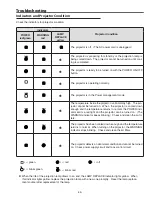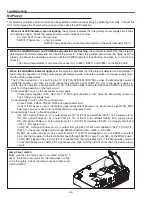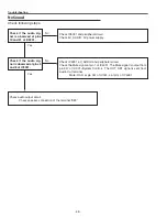
-47-
Troubleshooting
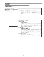
No Picture
No picture with all of in-
put sources
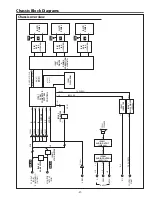
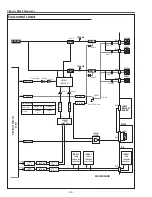
Check signal processing stage and LCD driving stage;
Check RGB S&H signals at test points TPB1, TPG1, TPR1.
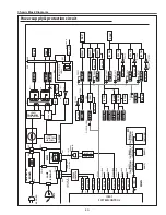
Check power supply circuit 15.5V and peripheral circuit.
Check ICs IC501, IC531, IC561, IC401, IC301 and peripheral
circuits.
Yes
No
check following steps.
Check each signal input stage;
Computer source
Check RGB signals.
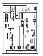
R signal is applied to pin 8 of IC301<System Control>, G sig-
nal is applied to pin 60 and B signal is applied to pin 58 of IC
301.
HV sync signals are applied to pins 331 and 161 of IC301<System
Control> as the HS and VS signals.
S-Video source
Check S-video signal (Y/C).
S_CHROMA signal is applied to pin 65 of IC301<System Con-
trol>, and S_Y signal is applied on pin 64 of IC301.
Component video source
The component signals are applied to pins 8, 58, 409 of
IC301<System Control>.
Composite video source
Check composite video signal (Video).
The composite video signal is applied to pin 6 of IC301<System
Control>.
Summary of Contents for 1 122 356 20
Page 18: ... 18 Optical Parts Disassembly m Optical Unit Top removal M3x8 x5 Optical top Fig 7 ...
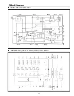
Page 53: ... 53 IC Block Diagrams FA5502 P F Control IC621 L3E6100D D A S H LCD Driver IC501 IC531 IC561 ...
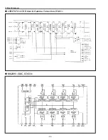
Page 54: ... 54 IC Block Diagrams L3E07072 LCD Driver Gamma Correction IC401 M62393 DAC IC3531 ...
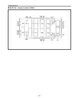
Page 55: ... 55 IC Block Diagrams NJW1141 Audio Control IC5001 ...
Page 81: ...KR6 XW55A00 KP6 XW50A00 81 Mechanical Parts List ...
Page 82: ... KR6AD Jun 2007 DC 350 Printed in Japan SANYO Electric Co Ltd ...

