background image

Maintenance Procedures

SY75C Excavator OMM

5-42

Operation and Maintenance Manual — 0220

SANY

5. If necessary remove oil filler cap (d), add oil as needed, 

then reinstall the cap.

6. Close the engine cover.

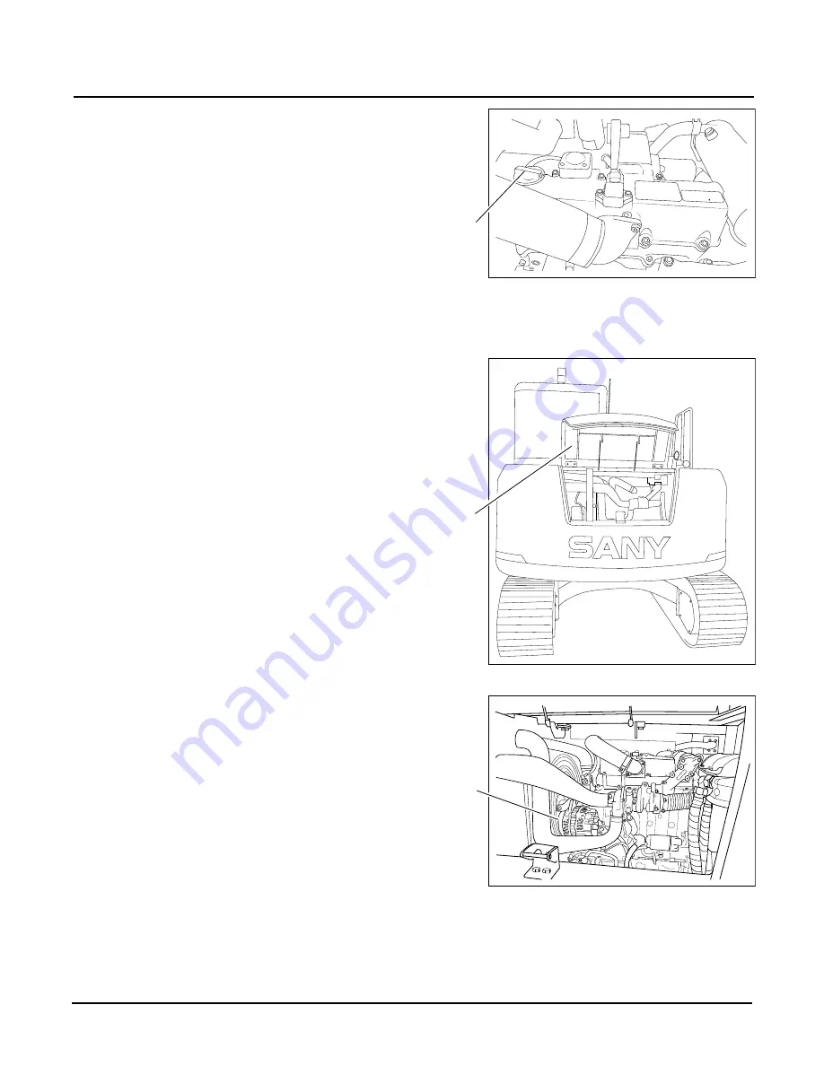
Engine V Belts - Check

1. Open engine cover (a).

2. Locate V belts (b). 

NOTE: 

There are two V belts, one driving the alternator 

and the other driving the air conditioning 
compressor.

3. Compare the information here with the actual belt.

a.  Abrasion

: The belt appears shiny, glazed or fabric is 

exposed. This is a sign that the belt is in contact with 
an object such as a flange or bolt.

b.  Chunk out

: Chunks of rubber material have broken 

off from the belt. At this stage, the belt can fail at 
any moment. Heat, age and stress are the primary contributors.

NOTICE!

Do not overfill the engine with oil. Failure to


observe and follow this directive may result in


severe damage to the engine.

Fig. 5-52

d

a

Fig. 5-53

Fig. 5-54

b

Summary of Contents for SY75

Page 1: ...service sanyamerica com SANY Part Number SSY005081688 SY75 Excavator Operation and Maintenance Manual ...

Page 2: ......

Page 3: ...or Operation and Maintenance Manual WARNING Read and understand all safety precautions and instructions in this manual before reading any other manuals provided with this machine and before operating or maintaining it Failure to do this could result in death or injury ...

Page 4: ...ANY 7269 www sanyamerica com find a dealer 2020 by SANY America Inc All rights reserved No part of this publication may be reproduced used distributed or disclosed except for normal operation and maintenance of the machine as described herein All information included within this publication was accurate at the time of publication Product improvements revisions etc may result in differences between...

Page 5: ...ine Operation 1 5 Maintenance 1 5 Specifications 1 5 Optional Equipment 1 5 Serial Number Location 1 6 Record of Serial Number and Dealer Information 1 6 Correction Request Form 1 7 Safety General Precautions 2 2 Hazard Alerts in This Manual 2 2 Preparations for Work 2 3 Precautions During Work 2 3 Lifting Precautions 2 4 Operator Safety Information 2 5 Mount and Dismount the Machine 2 5 Unauthori...

Page 6: ...3 12 Work Lamp Switch 3 12 Windshield Wiper Switch 3 13 Windshield Washer Switch 3 13 12V Power Supply 3 13 Emergency Stop 3 14 Joystick Controls 3 14 SAE BHL Joystick Operating Modes 3 14 SAE BHL Selector 3 14 SAE Mode 3 16 BHL Mode 3 17 Left Joystick Buttons 3 18 Right Joystick Buttons 3 19 Travel Controls 3 20 Auto Deceleration Function 3 21 Fuses 3 21 Monitor 3 23 Screen Displays 3 25 Main Ope...

Page 7: ...ine Procedures 4 10 Cold Weather Operation 4 10 Jump Start the Engine 4 11 Engine Start Procedure 4 12 Idle the Engine 4 13 Engine Shutdown Procedure 4 14 Machine Warm Up 4 15 Travel Operations 4 17 Before Travel 4 17 Track Direction 4 18 Right Turn 4 18 Left Turn 4 19 Straight Travel 4 19 Left Zero Radius Turn 4 19 Right Zero Radius Turn 4 20 Slopes 4 20 Operations in Water 4 20 Release Machine f...

Page 8: ...t Oil Samples 5 5 Weld Drill Cut or Grind on the Machine 5 5 Clean Parts or the Machine 5 6 Covers and Locks 5 6 Inspection and Maintenance in Adverse Environments 5 6 Mud Rain or Snow Conditions 5 6 Near Ocean Salt Air Environments 5 6 Dusty Environments 5 7 Rocky Ground Surface 5 7 Cold Environments 5 7 Other Weather Environments 5 7 Fluids and Lubricants 5 8 Location Capacity Type 5 8 Fuel 5 9 ...

Page 9: ... Coolant Level Check 5 35 Engine Exhaust Pipe Clamps Check 5 36 Collect Engine Oil Sample 5 36 Engine Oil and Filter Replace 5 37 Engine Oil Level Check 5 41 Engine V Belts Check 5 42 Escape Tool Check 5 43 Final Drive Check 5 44 Final Drive Gearbox Oil Level Check 5 44 Collect Final Drive Oil Sample 5 45 Final Drive Motor Mounting Bolts Check 5 45 Final Drive Oil Change 5 46 Fire Extinguisher Che...

Page 10: ...ack Assemblies Check 5 85 Track Bolts Check 5 86 Track Tension Check and Adjust 5 86 Track Tension Check 5 86 Track Tension Increase 5 88 Track Tension Reduce 5 89 Upper Structure and Lower Structure Check 5 89 Windshield Washer and Windshield Wiper Check 5 90 Work Equipment Lubricate 5 91 Machine Storage 5 96 Short Term Storage Less than 30 days 5 96 Long Term Storage Longer than 30 days 5 96 Spe...

Page 11: ... 0220 0 vii TABLE OF CONTENTS INTRODUCTION SAFETY MACHINE CONTROLS MACHINE OPERATION MAINTENANCE SPECIFICATIONS OPTIONAL EQUIPMENT Optional Equipment Operation 7 6 Attach Optional Equipment 7 6 Optional Equipment Controls 7 8 Blade Control 7 9 Disconnect Optional Equipment 7 9 ...

Page 12: ...Table of Contents SY75C Excavator OMM 0 viii Operation and Maintenance Manual 0220 SANY This Page Intentionally Left Blank ...

Page 13: ...bout This Manual 1 3 Your Documentation Package 1 4 Operation and Maintenance Manual 1 4 Parts Manual 1 4 Maintenance Log 1 4 Organization of This Manual 1 5 Table of Contents 1 5 Introduction 1 5 Safety 1 5 Machine Controls 1 5 Machine Operation 1 5 Maintenance 1 5 Specifications 1 5 Optional Equipment 1 5 Serial Number Location 1 6 Record of Serial Number and Dealer Information 1 6 Correction Re...

Page 14: ...personnel Do not operate or work on this machine without first reading and understanding this Operation and Maintenance Manual supplied with the machine Store this Operation and Maintenance Manual in the operator cab If the Operation and Maintenance Manual is missing or damaged do not use the machine until a replacement has been obtained from your SANY dealer Failure to have and to refer to an ava...

Page 15: ...involved with this machine must read this manual periodically to remain knowledgeable about its operation and maintenance Items addressed in this manual are designed to help you Understand the different systems and performance of your machine Reduce improper operation Point out possible hazardous situations when operating and maintaining the machine Increase machine efficiency during operation Pro...

Page 16: ...e operator cab a at all times A copy of this manual should be made available to maintenance personnel when maintaining the machine Parts Manual The Parts Manual consists of parts lists and matching drawings used for ordering spare parts as needed The Parts Manual is best left in the workshop area or office It should be available to the maintenance and service personnel Maintenance Log The Maintena...

Page 17: ...st of this manual including serial number information and SANY contact information Safety General and product specific safety information relating to this machine It describes what the hazard alerts that are used throughout the manual mean Machine Controls Overview of all controls and operating systems Machine Operation Detailed perstart checks operating procedures and end of day checks and storag...

Page 18: ...g replacement parts or providing assistance for your machine Record this information in this manual for future use Record of Serial Number and Dealer Information This location is for you to record information relating to your machine It is required that you keep this manual with your machine at all times for reference Machine Serial No Engine Serial No Right Final Drive Motor Serial No Left Final ...

Page 19: ...M If you find a problem with this manual make a copy of this page complete the form below and send it to us attention Technical Publications You can also email us at techpubs sanyamerica com Date of This Request Your Name Company Name Your Department Street Address City State and ZIP Phone E mail Machine Model and Serial No Description of Problem wrong information unclear or erroneous procedure et...

Page 20: ...Correction Request Form SY75C Excavator OMM 1 8 Operation and Maintenance Manual 0220 SANY This Page Intentionally Left Blank ...

Page 21: ... Precautions 2 4 Operator Safety Information 2 5 Mount and Dismount the Machine 2 5 Unauthorized Machine Modifications 2 6 Job Safety 2 6 Personal Protective Equipment PPE 2 7 Fire Safety 2 7 Dust and Chemical Hazards 2 7 Weld Drill Cut or Grind on the Machine 2 7 Oil Systems 2 7 Add Oils to the Machine 2 7 Refuel 2 8 High Pressure Oil Lines 2 8 Accumulator 2 8 Electrical System 2 8 Environmental ...

Page 22: ...ng this machine Hazard Alerts in This Manual Hazard alerts in this manual are used to alert operators job supervisors maintenance staff and job site workers to hazardous operating practices and maintenance procedures hazard alerts are used throughout this manual Each hazard alert contains a hazard alert symbol and a signal word to identify the hazard s degree of consequence if the message is ignor...

Page 23: ...fore starting the work hang Lockout Tagout tags in the operator s cab Keep all tools in good condition know how to use them and use the correct one Thoroughly check all tools before starting any procedure Before adding oil or making any repairs park the machine on a hard and level surface and block the tracks to prevent the machine from moving Before starting work lower the work equipment breaker ...

Page 24: ...nstalling hoses for high pressure circuits Make sure fittings are correctly installed When assembling or installing parts always tighten them to the specified torques When installing protective parts such as guards or parts which vibrate violently or rotate at high speed be particularly careful to check that they are installed correctly When aligning two or more parts never insert your fingers or ...

Page 25: ...rs are designed to alert the operator to potential problems Any faults found shall be reported to your SANY dealer Stop all work immediately if any operator aid is found to not be working properly Sole reliance on these operator aids in place of good operating practices can lead to an accident Inspect the operator aids of this machine daily and make sure each operator aid is in normal working cond...

Page 26: ...unning and unattended Always park the machine in a safe level area lower any work equipment to a safe position lock the controls to secure the machine to prevent tampering by unauthorized personnel and shut down the engine before exiting the machine even for a moment Before starting any work operations travel or maintenance procedures be sure all personnel are at a safe distance from the machine N...

Page 27: ...ntilated area Clean up any spilled fluids or coolant immediately Check the machine daily for excess debris buildup Dust and Chemical Hazards Performing operations and or encountering hazardous materials on the job site may release substances that could pose a hazard Exposure to hazardous chemicals or dusts poses a danger when they are released or mishandled All workers involved should use approved...

Page 28: ...s when checking for leaks and use a piece of wood or cardboard when checking leaks from small holes Check for cracks in the piping or hoses and for swelling in the hoses If there is any leakage from a line or hose the surrounding area will be wet Replace a line or hose if a leak is found or failure occurs If high pressure oils penetrate skin or get into eyes seek medical attention immediately Accu...

Page 29: ...es of water into storm drains or tossed into trash cans even in a sealed container can contaminate and pollute the soil groundwater streams and rivers Recycling used oils reduces this pollution threat Always drain oils from the machine into an appropriate container Drain crush and dispose of all filters properly Obey all local regulations when disposing of harmful items such as oil fuel filters ba...

Page 30: ...r SANY distributor can supply you with new replacement decals if needed Never modify or change existing decal information unless authorized by your SANY distributor When replacing decals be sure they are placed in the proper locations Please note that the decals shown in this manual may not exactly match what you have on your machine Contact your SANY dealer if you have any questions as to meaning...

Page 31: ...IPMENT 2 Crush Hazard Located on either side of the arm centered between the top and the bottom of the length of the arm Warns against being crushed by the machine arm or objects being lifted Advises to stay clear of overhead objects and machine components 3 Exit Located on the inside rear window of the cab centered toward the top Identifies an emergency exit out the back window Fig 2 6 Fig 2 7 ...

Page 32: ...the machine and to stay clear of the edge of the machine 5 Fan belt warning Located in the engine compartment near the fan belt Warns to turn the engine off to avoid getting caught in rotating parts 6 Fan warning Located in the engine compartment near the fan belt Warns about the rotating fan within the engine compartment Keep hands clear of the fan and all rotating components Fig 2 8 Fig 2 9 Fig ...

Page 33: ...nt window warning Located on the upper right corner of the front window Gives warning to make sure the front window is locked in place 9 Grease point pressure warning Located next to the opening for the track tensioning grease point on either side of the tracks Warns about grease spraying out under pressure from the track tensioner 10 High temperature warning Located in the engine compartment near...

Page 34: ...cated inside the cab on the right side of the operator on the window Identifies the danger of coming in contact with high voltage electrical wires stay away 12 No step warning Located on top of the engine hood Warns against falling off the machine and to not walk or step in this area Fig 2 15 Fig 2 16 ...

Page 35: ...tion of the valve 14 Pattern Change Located next to the SAE BHL Selector located behind the left rear access panel Gives guidance on how to switch the machine from SAE to BHL mode Warns about stopping the engine before switching modes 15 Pattern change instruction Located inside the cab on the window to the right of the operator Explains how the controls will react in SAE or BHL mode Be sure to kn...

Page 36: ...or cap Warns against opening the radiator when it is hot and under pressure 18 Seat belt Located inside the cab on the widow to the right of the operator Warns to fasten the seat belt before operating the machine 19 Track tension Located on the track frame Warns to read the manual before attempting to adjust track tension 20 Swing bearing grease Located in the front bottom right corner of the cab ...

Page 37: ... Adhere to the following Use only the designated lift points to lift the machine and designated tow points to tow the machine Be sure the lift and tow points are undamaged and in good working order Always tow or lift in the direction indicated by the decal If the decal is missing or damaged contact your SANY dealer for the proper procedures Always wear leather gloves when handling wire rope During...

Page 38: ...Tow or Lift the Machine SY75C Excavator OMM 2 18 Operation and Maintenance Manual 0220 SANY This Page Intentionally Left Blank ...

Page 39: ...l Panel 3 9 Right Control Console 3 11 Indicator Lights 3 11 Key Switch 3 12 Throttle Control Dial 3 12 Dozer Blade Control 3 12 Work Lamp Switch 3 12 Windshield Wiper Switch 3 13 Windshield Washer Switch 3 13 12V Power Supply 3 13 Emergency Stop 3 14 Joystick Controls 3 14 SAE BHL Joystick Operating Modes 3 14 SAE BHL Selector 3 14 SAE Mode 3 16 BHL Mode 3 17 Left Joystick Buttons 3 18 Right Joys...

Page 40: ...unning Information Screens 3 26 Engine and Throttle Signals Screen 3 26 Switch Signals Screen 3 27 Machine Configuration Screen 3 27 Failure Codes Screen 3 28 Maintenance Information Screens 3 28 GPS Information Screen 3 30 Language Selection Screen 3 31 Date and Time Setup Screen 3 31 ...

Page 41: ...E OPERATION MAINTENANCE SPECIFICATIONS OPTIONAL EQUIPMENT EXTERIOR COMPONENTS Fig 3 1 1 Bucket 9 Track shoe 2 Bucket cylinder 10 Track frame 3 Arm 11 Idler 4 Arm cylinder 12 Dozer blade cylinder 5 Boom cylinder 13 Dozer blade 6 Boom 14 Cab 7 Engine compartment 15 Windshield wiper 8 Drive Sprocket 16 Work Lamps 1 2 3 4 6 5 7 8 13 12 11 10 9 14 15 16 ...

Page 42: ...OMM 3 4 Operation and Maintenance Manual 0220 SANY CAB INTERIOR Fig 3 2 1 Left control console 5 Display 2 Left joystick 6 Right joystick 3 Foot rest 7 Right control console 4 Travel controls 8 Dozer blade control 3 2 1 4 3 5 6 7 8 ...

Page 43: ...ative to the control consoles The adjusting lever e adjusts the seat suspension Weight adjustment knob f Hydraulic Lockout Control Lever WARNING Always place the hydraulic lockout control lever in the LOCKED position before leaving the operator cab If this lever is not in the LOCKED position any unintended movement of the joysticks or travel control levers may cause death or injury Avoid moving ei...

Page 44: ...ckout control lever up into the UNLOCKED position The machine will now move in accordance with the joysticks and other control levers Left Control Console The left control console is to the left of the operator when seated The left control console contains the following items Left joystick a Hydraulic lockout control b Radio control panel c Climate control panel d Fig 3 4 UNLOCKED LOCKED OFF MODE ...

Page 45: ...ith the A C on press and hold both the up and down arrows for 3 seconds to toggle between Fahrenheit F and Celsius C temperature display Vent mode selection 4 Press this key to select which vent or vents should be used for air flow inside the cab Windshield vent only Upper body vent only Upper body and rear window vents Foot vent located under the operator seat upper body and rear window vents Foo...

Page 46: ...ither on or off Sunlight sensor a Located above the air conditioning duct adjusts the air flow to match the variation of temperature caused by direct sunlight A C Operation Precautions A C controller failure will be displayed on the air conditioner display screen if there is a problem with the a c unit If this occurs contact your SANY dealer to investigate and repair it NOTICE When running the air...

Page 47: ... allows for setting the treble pressing it once more allows for setting the balance between the in cab speakers and pressing it again allows for setting the volume The current radio station frequency displays if the button is not pressed within 5 seconds NOTE Use the VOL keys to increase and decrease the setting of the selected audio category Time display 4 Press this key to display the local time...

Page 48: ...key Afterwards press and release any of the keys to select its preselected station Pressing the ASPS key 5 longer than 2 seconds activates the auto scanning of all preselected stations The six radio stations with the strongest signal will be stored to the six Preset Station keys 1 6 Tuning key 8 Press this key to move either back to the previously set radio station or on to the next previously set...

Page 49: ... c not shown Work lamp switch d Windshield wiper switch e Windshield washer switch g Throttle control dial h Key switch k Indicator Lights Preheat indicator a The preheat indicator is normally off It will light when the keyswitch is set to the preheat position Charging indicator b The charging indicator is normally off to indicate the excavator is free from charging failure If this light starts to...

Page 50: ...osition to start the engine then immediately release it after the engine has started The key returns to the ON position when released Throttle Control Dial Throttle control dial b is used to adjust engine speed and output power Turn the dial clockwise to increase speed and counterclockwise to decrease speed Low Idle MIN Turn it counterclockwise to the end Full Speed MAX Turn it clockwise to the en...

Page 51: ...w of fluid stops and the switch returns to its off position when released 12V Power Supply This 12 volt socket a can be used to charge your mobile phone or other 12 volt items of equipment NOTICE Ensure that the windshield of the cab is closed before activating the windshield wiper Damage to the wiper blade wiper arm or wiper motor may result if the wiper is activated with the windshield open Use ...

Page 52: ...ciety of Automotive Engineers mode BHL Backhoe Loader mode SAE BHL Selector WARNING Never extend any part of your body outside the operator cab window while the machine is running Know the positions and functions of each joystick Failure to observe and follow this warning may cause unexpected movement of the machine which could result in death or injury NOTICE Shut down the engine before adjusting...

Page 53: ... of the boom and the arm from one joystick to the other The position shown is the SAE mode position b To change to the BHL position pull up on the pin and rotate the bar to the right c Release the pin to lock the bar in place In SAE Society of Automotive Engineers mode the arm is controlled using the left joystick and the boom using the right joystick In BHL Backhoe Loader mode the arm is controll...

Page 54: ... and Maintenance Manual 0220 SANY SAE Mode Fig 3 18 Front Swing Left Swing Right Left Front Right Bucket Dig Boom DOWN Bucket Dump Boom UP Arm IN Arm OUT Front Front NOTE When the joystick is released it returns to neutral and machine movement stops ...

Page 55: ...TION SAFETY MACHINE CONTROLS MACHINE OPERATION MAINTENANCE SPECIFICATIONS OPTIONAL EQUIPMENT BHL Mode Front Boom DOWN Swing Left Swing Right Boom UP Left Front Right Bucket Dump Arm IN Bucket Dig Arm OUT Fig 3 19 Front Front NOTE When the joystick is released it returns to neutral and machine movement stops ...

Page 56: ...ck Buttons The left joystick contains two buttons which are being reserved for future use NOTE Starting with serial number 15SY0075R0618 left joystick a has been replaced with a different joystick b Button functionality has not changed none of the buttons are operational Fig 3 20 a Fig 3 21 b ...

Page 57: ...ONAL EQUIPMENT Right Joystick Buttons The right joystick contains two buttons Button a activates the horn Button b is a spare and is not used NOTE Starting with serial number 15SY0075R0618 right joystick has been replaced with a different joystick c Button d activates the horn button e is not operational and button f is used to control optional equipment Fig 3 22 a b Fig 3 23 d e f c ...

Page 58: ...ering control levers b Steering control pedals c NOTE Footrests d is not a control device NOTE When a steering control lever or joystick is released it returns to neutral position and machine movement stops WARNING Take extra care when using the pedals to steer the machine Never rest your foot on a pedal unless you are driving or steering the machine Failure to observe and follow this warning coul...

Page 59: ...ation function works as described below If the joysticks and travel controls remain in their neutral positions for at least 5 seconds the engine speed drops from the current speed to the factory set auto idle speed approximately 1 350 50 rpm NOTE If the engine speed is set to below the factory set auto idle speed the auto deceleration function will not change the engine speed If either of the joys...

Page 60: ...F11 Cab rear light 10A F14 Monitor controller 15A F13 Power converter 15A F16 Solenoid 20A NOTICE When performing a battery disconnect wait for at least one full minute before disconnecting the battery so the machine ECM can complete the shutdown procedure Before replacing a fuse make sure that the key switch is in the OFF position and the batteries disconnected Always replace a fuse with one of t...

Page 61: ...MAINTENANCE SPECIFICATIONS OPTIONAL EQUIPMENT MONITOR When the key switch is turned to the ON position the monitor is energized A display of the monitor home screen is shown below Fig 3 29 1 LCD display 3 Function keys 2 Function icons 4 Navigation keys F1 F2 F3 F4 Esc Enter S Sany Hydraulic Excavator S1 h m 00006 20 14 30 20 2013 12 09 A B 4 3 2 1 ...

Page 62: ...nal indicator 3 Working mode 11 High Low speed shift F3 4 Throttle position prompt location 12 Maintenance prompt location 5 Local date 13 Fault code location 6 Battery indicator 14 Auto deceleration function Off On F2 7 Fuel level 15 Working mode F1 8 Local time S Sany Hydraulic Excavator S1 h m 00006 20 14 15 21 2013 12 09 1 2 3 6 7 8 9 10 11 15 13 2 14 12 4 5 ...

Page 63: ...n when a code is shown Press the up arrow key to display the Service Call screen Press the right arrow key to display a maintenance screen only when the maintenance icon is displayed Password Screen Enter the password before accessing the system information screens Attempting to display any screen other than the Failure Codes screen will display the Password screen Each digit is indicated by an as...

Page 64: ... follow Running Information Screens There are two separate Running Information screens the Engine and Throttle Signals and the Switch Signals screen To toggle between these screens press F1 or press the up or down arrows Engine and Throttle Signals Screen The Engine Signals screen displays Throttle Volt V Displayed volts Fuel level Displayed as full Engine oil press Pressure displayed in PSI or Kg...

Page 65: ...art Input Air Cleaner Plugged Shutdown Input Hi Lo Speed Input Start Output Preheat Output Shutdown Output Hi Lo Speed Output Press F1 or the up or down arrows to cycle through the running parameter screens Press F4 to display the main operator screen Machine Configuration Screen The Machine Configuration screen displays Machine Model Machine S N Control System Press F4 to display the main operato...

Page 66: ...ired The pop up block will disappear after one minute The popup will not display during operation There are six Maintenance Information screens one each for the six maintenance intervals Daily 50 Hours 250 Hours 500 Hours 1000 Hours and 2000 Hours of service that list the scheduled maintenance procedures on the maintenance information screens Current Failure Code Failure Codes Get failure informat...

Page 67: ... REPLACE Fig 3 39 MAINTENANCE INFORMATION 500 H MAINTENANCE SCHEDULE 1 250 HOUR MAINTENANCE 2 SWING BEARING LUBRICANT ADD 3 SWING BEARING INTERNAL GEAR LUBRICANT ADD 4 TRAVEL REDUCER ASSY GEAR OIL LEVEL CHECK 5 RETURN SUCTION PILOT FILTER ELEMENT REPLACE 6 FAN BELT TENSION ADJUST 7 RADIATOR INSIDE OUTSIDE SURFACE CLEAN 8 TRACK DEFLECTION CHECK 9 OIL COOLER FRONT STRAINER CLEAN 10 AIR CLEANER ELEME...

Page 68: ...rmal Press F4 to display the main operator screen NOTE When the altitude display is not zero and both the longitude and latitude display 0 the system is processing the signals to provide a precise location NOTE When Indication changes to 0 from 7 it means that there is a connection loss in the SIM card or the antenna may be inoperative When the Indication changes to 0 from 15 it means that the GPS...

Page 69: ... Press F2 to set the system to English Press F4 to display the main operator screen Date and Time Setup Screen The Date and Time Setup screen displays the current date and time Press the up and down arrows to change the digits shown in the display Press the right and left arrows to move between positions Press F3 or Enter to accept the information inputted Press F4 to display the Main Menu NOTE Us...

Page 70: ...Monitor SY75C Excavator OMM 3 32 Operation and Maintenance Manual 0220 SANY This Page Intentionally Left Blank ...

Page 71: ...nitor Settings 4 7 First Time Setup 4 7 Access the Main Menu 4 7 Language Selection 4 9 Time and Date Display 4 9 Engine Procedures 4 10 Cold Weather Operation 4 10 Jump Start the Engine 4 11 Engine Start Procedure 4 12 Idle the Engine 4 13 Engine Shutdown Procedure 4 14 Machine Warm Up 4 15 Travel Operations 4 17 Before Travel 4 17 Track Direction 4 18 Right Turn 4 18 Left Turn 4 19 Straight Trav...

Page 72: ...4 Arm 4 24 Boom 4 24 Bucket 4 25 Recommended Applications 4 26 Backhoe Operation 4 26 Digging a Trench 4 27 Loading Operations 4 27 End of Workday Checks 4 28 Park and Store the Machine 4 29 Overnight Storage 4 29 Short Term Storage 4 30 Long Term Storage 4 30 Preparation 4 30 During Storage 4 32 Return to Service 4 33 Transport the Machine 4 34 Lift the Machine 4 34 Load the Machine 4 34 Unload t...

Page 73: ... where personnel may be at risk due to machine operation or movement Those within the work area must wear personal protective equipment The safety of all personnel within the hazard area is the responsibility of the machine operator General Job Safety NOTE See Job Safety on page 2 6 WARNING Do not move the machine onto a surface or area that has not been approved for the machine The machine is hea...

Page 74: ... devices Know basic information about the systems of this machine Know and use the correct hand signals between the machine operator and a signal person Stop machine operations in case any defects endangering safety are found The operator must control the machine to protect the personnel or other facilities in the vicinity of the machine Ensure that all control devices are set to neutral or idle p...

Page 75: ...s much as possible in the half to three quarters throttle or load range Keep the engine speed at or near idle until the engine reaches its normal operating temperature Avoid long periods of operation with the engine at idle or continuous maximum horsepower levels Avoid sudden starts movements or stops Manage engine power to a point that allows acceleration to governed speed when conditions require...

Page 76: ...ctions have not been performed notify your supervisor Clean 1 Make sure these items are cleaned Windows a Mirrors b Grab handles c Steps d 2 Remove all trash from inside the cab to avoid interference with operation of the machine CAUTION Perform this inspection and have needed issues resolved before operation Failure to observe and follow this caution could result in minor or moderate injury CAUTI...

Page 77: ...NTROLS MACHINE OPERATION MAINTENANCE SPECIFICATIONS OPTIONAL EQUIPMENT MONITOR SETTINGS Monitor a is mounted in the front right of the cab First Time Setup Access the Main Menu 1 Turn ignition key a to the ON position NOTE Main Screen displays Fig 4 2 a Fig 4 3 a S Sany Hydraulic Excavator S1 h m 00006 20 14 15 21 2013 12 09 Fig 4 4 ...

Page 78: ...intenance Manual 0220 SANY 2 Press F4 b and the System Information screen displays 3 Enter the password digits F1 F2 F3 F4 Esc Enter S Sany Hydraulic Excavator S1 h m 00006 20 14 30 20 2013 12 09 A B Fig 4 5 b System Information Please enter password Fig 4 6 ...

Page 79: ...ONAL EQUIPMENT 4 Press Enter to accept Password and then F4 to access the Main Menu Language Selection NOTE See Language Selection Screen on page 3 32 Time and Date Display NOTE See Date Time Setup Screen on page 3 32 System Information Running Information Machine Configuration Failure Information Maintenance Information GPS Information Engine Speed Calibration Language Selection Fig 4 7 ...

Page 80: ...ine must have appropriate hydraulic oil lubricants and other auxiliary items required for operation in sub zero temperatures Individual machine functions should be operated to ensure they are sufficiently warmed prior to performing work Operation of machine at full rated capacities in temperatures between 0 F 18 C and 40 F 40 C or lower should be accomplished only by competent operators who posses...

Page 81: ... contacts your skin or your eyes flush the area immediately with fresh water and seek medical attention Failure to observe and follow this caution could result in injury NOTICE The starting system voltage and the battery voltage in the boosting machine should be no more than 24V Never use a welder or equipment with a higher voltage system to jump start the machine Using a higher voltage to jump st...

Page 82: ...harged battery and run it at medium speed 7 Attempt to start the engine of the machine with the drained battery Retry every three minutes if the engine will not start NOTE Contact your SANY dealer if the engine will not start after five attempts 8 Disconnect the jumper cables from the machine that had the drained battery in reverse order as shown above 9 Disconnect the cables from the machine with...

Page 83: ...or assistance 6 Check the engine instruments and monitor for any alarm codes after starting Shut down the engine if a failure code is displayed on the display screen Idle the Engine Idling the engine for long periods of time wastes fuel Unburned fuel causes carbon formation oil dilution formation of lacquer or gummy deposits on the valves pistons and rings and rapid accumulation of sludge in the e...

Page 84: ...e ignition key a to the OFF position NOTICE Except for emergencies never shut down the engine while it is running at high speed Stopping the engine at high speed can cause damage to the machine or cause the machine to operate improperly NOTICE If performing a battery disconnect wait for at least one full minute before disconnecting the battery cables so the machine ECM can complete its updating pr...

Page 85: ... 1 400 rpm then slowly operate the bucket for five minutes 6 Adjust the throttle to run the engine at high speed about 2 000 rpm then operate the boom arm and bucket for 5 10 minutes 7 Cycle each action of the machine several times NOTICE Do not begin machine operation immediately after starting the engine Perform the following warm up procedures to prepare the system for operations Failure to do ...

Page 86: ... 0220 SANY 8 Continue to warm up the machine until the coolant temperature reaches the middle of display a on the monitor 9 Press F1 b to select the desired working mode c F1 F2 F3 F4 Esc Enter S Sany Hydraulic Excavator S1 h m 00006 20 14 30 20 2013 12 09 A B Fig 4 10 b c a ...

Page 87: ...er b in the UNLOCKED position 3 Ensure good visibility WARNING Never allow any personnel to be within 26 ft 8 m of the machine while it is moving Be aware of all crush points on the machine and ensure that all personnel keep clear of these areas Avoid moving any control lever or pedal to abruptly change the direction of the machine Avoid stopping the machine suddenly by releasing the lever or peda...

Page 88: ...he cab faces backward the machine moves forward when you pull control levers and backward when you push them SANY does not recommend traveling with the carriage reversed Always keep in mind the travel lever controls will be working in the opposite direction from normal travel Right Turn Move the left travel control lever to cause the left track to move forward or backward depending on which direct...

Page 89: ...of the right track is shown in the illustration The further the control is moved in either direction the faster the right track moves Straight Travel Fig 4 50 Move both controls at the same time to cause both tracks to move forward or backward depending on which direction the control is moved NOTE Forward direction of both tracks is shown in the illustration The further the controls are moved in e...

Page 90: ...ght subject the machine to undue stresses and possible tipover Position the bucket 16 20 in 20 30 cm above the ground while traveling Always set the throttle control dial to maintain a slow speed while traveling up or down a slope Do not turn the machine while on a slope Do not travel in reverse on a slope Operations in Water Observe the following when operating the machine in water Do not drive t...

Page 91: ...rive the machine out of the mud Two Tracks Stuck 1 Position the boom and arm at an angle between 90 and 110 2 Pivot the upper structure to position the boom over the front of the machine 3 Curl the bucket so that the back of the bucket contacts the ground NOTE Use cribbing to provide a firm surface if necessary 4 Lower the boom to lift the front of the tracks 5 Place cribbing under the tracks 6 Cu...

Page 92: ...g the work equipment to the right NOTE The swing function is the same for SAE and BHL Arm Move the left joystick forward to extend the arm Move the left joystick rearward to retract the arm WARNING Never allow any personnel to be within 26 ft 8 m of the rear of the machine while it is moving Be aware of all crush points on the machine and ensure that all personnel keep clear of these areas Failure...

Page 93: ...NE OPERATION MAINTENANCE SPECIFICATIONS OPTIONAL EQUIPMENT Boom Move the right joystick forward to lower the boom Move the right joystick rearward to raise the boom Bucket Move the right joystick to the left to curl the bucket Move the right joystick to the right to dump the bucket NOTE The bucket function is the same for SAE and BHL Fig 4 55 Fig 4 56 ...

Page 94: ... work equipment to the left Move the left joystick to the right to swing the work equipment to the right NOTE The swing function is the same for SAE and BHL Arm Move the right joystick forward to extend the arm Move the right joystick rearward to retract the arm Boom Move the left joystick forward to lower the boom Move the left joystick rearward to raise the boom Fig 4 57 Fig 4 58 Fig 4 59 ...

Page 95: ...LE OF CONTENTS INTRODUCTION SAFETY MACHINE CONTROLS MACHINE OPERATION MAINTENANCE SPECIFICATIONS OPTIONAL EQUIPMENT Bucket Move the right joystick to the left to curl the bucket Move the right joystick to the right to dump the bucket NOTE The bucket function is the same for SAE and BHL Fig 4 60 ...

Page 96: ...inder and the bucket linkage are both 90 WARNING Contact the site supervisor before any digging to ensure that all underground hazards have been located Failure to observe and follow this warning could result in death or injury Never allow any personnel to be within 26 ft 8 m of the machine while it is moving Be aware of all crush points on the machine and ensure that all personnel keep clear of t...

Page 97: ...E SPECIFICATIONS OPTIONAL EQUIPMENT Digging a Trench Trench work can be done efficiently by using a suitable bucket and positioning the tracks parallel to the trench line When digging a wider trench excavate the sides first then remove the middle Loading Operations It is more convenient to load material if the truck is loaded from the rear than from the side Fig 4 63 Fig 4 64 ...

Page 98: ...h can 2 Remove all built up mud or debris on the lower structure and machine exterior 3 Inspect the machine work equipment machine exterior and lower structure for signs of fluid leaks or damage 4 Near ocean salt air environments thoroughly wash away any salt residue apply grease where rust is found and perform maintenance on the electrical components to prevent corrosion Fig 4 65 ...

Page 99: ...in hot weather 4 Turn the ignition key to the OFF position 5 Remove the ignition key when the engine comes to a complete stop 6 Place hydraulic lockout control lever a in the LOCKED position 7 Close and lock the windows 8 Exit the cab and lock the cab door 9 Fill the fuel tank 10 Ensure that the following items are secured and locked Cab door c A C fresh air inlet door d Left rear door e NOTICE If...

Page 100: ... 30 days or less Long Term Storage Proper preparation for long term storage will reduce the chances for damage or deterioration of the machine NOTE Long term storage is defined as a storage period of more than 30 days Preparation 1 Park the excavator in a secure location and position the work equipment with the arm and bucket fully extended 2 Run the engine at idle speed for about five minutes to ...

Page 101: ...aulic lockout control lever a in the LOCKED position 5 Close and lock the windows 6 Exit cab b 7 Turn both of the outside rear view mirrors inward so that they are within the perimeter of the machine NOTE Mirror d is cab mounted The other mirror is attached to the right side of the upper structure see Exterior Components on page 3 3 for mirror locations 8 Fill the fuel tank Fig 4 18 a UNLOCKED LOC...

Page 102: ...store them in a separate location During Storage Once a month 1 Start the machine NOTICE When performing a battery disconnect wait for at least one full minute before disconnecting the battery cables so the machine ECM can complete its updating procedure Failure to observe and follow this notice can cause damage to the machine or cause the machine to operate improperly WARNING When operating the m...

Page 103: ... the seals 4 Coat the exposed parts of the cylinder rods with spray lubricant to prevent corrosion 5 Turn on the air conditioner and allow it to run for 3 to 5 minutes to lubricate the compressor and related parts 6 Return the machine to the proper storage location and condition Return to Service 1 Check the fuel and engine oil for water contamination Drain water or replace fluids as necessary 2 E...

Page 104: ... or less 4 Position the machine so that the centerline of the machine matches the centerline of the trailer 5 Set auto deceleration to OFF NOTE See Main Operator Screen on page 3 25 6 Set travel speed mode to slow WARNING To avoid a machine tip over condition do the following when loading or unloading Select a firm and level location a safe distance from any road or structure Ensure that the trail...

Page 105: ...d for about five minutes to allow for heat dissipation if necessary NOTE Extend this cool down time in hot weather 10 Turn the key switch to the OFF position 11 Remove the key from the key switch when the engine comes to a complete stop 12 Place the hydraulic lockout control lever in the LOCKED position 13 Close and lock the windows 14 Exit the cab and lock the cab door 15 Ensure that the followin...

Page 106: ...cle with suitable tie downs in accordance with all applicable laws and regulations Unload the Machine 1 Verify that the vehicle wheels are properly chocked 2 Verify that the ramp to the vehicle has adequate strength and width and has a slope of 15 degrees or less 3 Remove all tie downs securing the machine to the vehicle 4 Turn the exterior rear view mirrors 5 Remove the exhaust covering 6 Unlock ...

Page 107: ...FF NOTE See Main Operator Screen on page 3 25 8 Set travel speed mode to slow NOTE See Throttle Control Dial on page 3 12 9 Place the hydraulic lockout control lever in the UNLOCKED position 10 Raise the work equipment to clear the trailer 11 Drive the machine slowly off the trailer 12 Keep the work equipment as low as possible as the machine moves forward off the ramp 13 Park the machine at the d...

Page 108: ...Transport the Machine SY75C Excavator OMM 4 38 Operation and Maintenance Manual 0220 SANY This Page Intentionally Left Blank ...

Page 109: ...r the Machine 5 6 Covers and Locks 5 6 Inspection and Maintenance in Adverse Environments 5 6 Mud Rain or Snow Conditions 5 6 Near Ocean Salt Air Environments 5 6 Dusty Environments 5 7 Rocky Ground Surface 5 7 Cold Environments 5 7 Other Weather Environments 5 7 Fluids and Lubricants 5 8 Location Capacity Type 5 8 Fuel 5 9 Engine Oil Viscosity Temperature Data 5 9 Lubricating Grease Temperature D...

Page 110: ...Level Check 5 35 Engine Exhaust Pipe Clamps Check 5 36 Collect Engine Oil Sample 5 36 Engine Oil and Filter Replace 5 37 Engine Oil Level Check 5 41 Engine V Belts Check 5 42 Escape Tool Check 5 43 Final Drive Check 5 44 Final Drive Gearbox Oil Level Check 5 44 Collect Final Drive Oil Sample 5 45 Final Drive Motor Mounting Bolts Check 5 45 Final Drive Oil Change 5 46 Fire Extinguisher Check 5 48 F...

Page 111: ...ser Fins Check 5 77 SAE BHL Selector Switch Set 5 78 Seat Belt Check 5 79 Sheet Metal Check 5 80 Swing Bearing Lubricate 5 80 Swing Bearing Bolts Check 5 81 Swing Drive Check 5 81 Swing Drive Oil Change 5 82 Swing Gearbox Bearing Lubricate 5 84 Swing Grease Bath Level Check 5 84 Top Roller Bolts Check 5 85 Track Assemblies Check 5 85 Track Bolts Check 5 86 Track Tension Check and Adjust 5 86 Track...

Page 112: ... contact with you at all times Contact your SANY dealer if you are unable to perform the procedures listed in this manual or if additional procedures are required Always use the proper tools when performing any maintenance procedures Checks After Maintenance or Repairs Always do the following after performing any maintenance to the machine Ensure all steps listed in this book have been followed If...

Page 113: ...xing different lubricant brands or viscosities may result in shortened service life or system failure of the machine Collect Oil Samples Collect and send oil samples for testing in accordance to the maintenance schedule Obtain and follow the instructions within an Oil Analysis Sample Kit from a SANY dealer Weld Drill Cut or Grind on the Machine NOTE Contact your SANY dealer for proper guidance on ...

Page 114: ...ions Check and clean any electrical components to avoid any accumulated corrosion Check and clean any areas where extreme heat is present such as the exhaust system manifold and turbocharger For heavy load operation and deep excavation add grease to the pins of the work equipment prior to each operation Cycle the operation of the boom arm and bucket several times before refilling with additional g...

Page 115: ... applies to metal track only SANY does not recommend using rubber track on rocky ground surface Cold Environments In extremely cold environments below 32 F 0 C lubricate only with the oils shown in Engine Oil Viscosity Temperature Data on page 5 9 SANY recommends the use of fuels identified in Fluids and Lubricants on page 5 8 for extremely cold environments Prior to starting the engine ensure tha...

Page 116: ...of this type are manufactured by Isuzu Caltex Chevron Shell Elf Total Castrol BP Idemitsu and Exxon Mobil Fuel system 39 6 gal 150 L 2 Diesel Fuel or mixtures of 2 Diesel and 1 Diesel Fuels in cold weather conditions Engine Cooling System 3 2 gal 12 L See Hydraulic Oil Ambient Temperature Data on page 5 10 SANY recommends brands that include Isuzu Zerox and Valvoline Swing gearbox 1 06 gal 4 0 L S...

Page 117: ...should occur in the fuel system contact your SANY dealer Be sure that there is no water or any foreign material in the fuel Take appropriate precautions to prevent fuel contamination during refueling NOTE B5 Biodiesel blend has been approved by Isuzu for Tier 4i engines Engine Oil Viscosity Temperature Data DANGER Never maintain the fuel system near an open flame or while smoking Failure to follow...

Page 118: ...0 68 20 86 30 104 40 122 50 220 LS2 85W 140 NOTE Any brand meeting AGMA standard 9005 D94 ISO 3448 grade 220 is acceptable Short term use of low viscosity engine oil in cold temperatures below 23 F 5 C promotes engine life long term use of low viscosity engine oil can reduce engine life Temperature F C Oil Type 22 30 4 20 14 10 32 0 50 10 68 20 86 30 104 40 122 50 ISO VG 46 antiwear hydraulic oil ...

Page 119: ...ty bearings and general industrial lubrication Heavy duty plain and rolling element bearings operating under severe conditions including shock loading in wet environments NOTICE To prevent damage to the hydraulic system perform the following warm up procedure in ambient temperatures below 32 F 0 C Start the engine and run it at idle speed for 7 10 minutes then increase the engine speed to 1 000 1 ...

Page 120: ... Washer Fluid Use clean automotive windshield washer fluid only Do not mix concentrates into the windshield washer fluid NOTICE Never use tap water dirty water or fluids that could freeze clog or damage the system Using these fluids could result in damage to the machine and improper machine operation ...

Page 121: ...itioning Fresh Air Filter Check See page 5 19 Hydraulic System Breather Filter Replace See page 5 64 Radiator Oil Cooler and A C Condenser Fins Check See page 5 77 Daily or 10 Hour Decals Check See page 5 24 Sheet Metal Check See page 5 80 Idler Check See page 5 67 Primary Fuel Filter Drain See page 5 75 Pump Mounting Bolts Check See page 5 76 Hydraulic Oil Tank Level Check See page 5 61 Hydraulic...

Page 122: ...Check See page 5 71 Air Conditioner Check See page 5 17 Operation and Maintenance Manual Check See page 5 72 Weekly or 50 Hour Engine Oil and Filter Replace See page 5 37 Work Equipment Lubricate See page 5 91 Engine Air Intake System Check See page 5 29 Batteries Check See page 5 21 Hydraulic Hoses Check See page 5 51 Final Drive Motor Mounting Bolts Check See page 5 45 Final Drive Gearbox Oil Le...

Page 123: ...shield Wiper Check See page 5 90 Electrical System Check See page 5 25 Air Conditioner Compressor Belt Check and Adjust See page 5 18 3 Months or 500 Hour Upper Structure and Lower Structure Check See page 5 89 See Swing Bearing Lubricate on page 5 80 Final Drive Check See page 5 44 Hydraulic Hoses Check See page 5 51 Radiator Oil Cooler and A C Condenser Fins Check See page 5 77 Hydraulic System ...

Page 124: ...ce See page 5 63 Hydraulic Tank Return Filter Replace See page 5 65 Fuel Lines Check See page 5 49 Engine Exhaust Pipe Clamps Check See page 5 36 Annually or 2 000 Hour Upper Structure and Lower Structure Check See page 5 89 Swing Bearing Bolts Check See page 5 81 Final Drive Oil Change See page 5 46 Hydraulic Oil Change See page 5 56 Engine Coolant Change See page 5 32 At the completion of the ma...

Page 125: ...sure remaining in the hydraulic lines NOTE If the machine does not move after cycling the pedal joystick and control lever contact your SANY dealer 6 Start the engine and let it run for about five minutes to pressurize the accumulator Air Conditioner Check With the engine running press air conditioning fan switch a inside the cab to check startup air flow and fan speed control CAUTION Hydraulic oi...

Page 126: ...3 lbf 637 N for a new belt and a force of 99 lbf 441 N for a used belt The belt must deflect 1 0 20 in 0 31 in 5 mm 8 mm 5 Adjust belt tension if necessary 6 Replace the shroud and secure in place Air Conditioner Compressor Belt Adjust 1 Remove the shroud 2 Loosen adjustment screw a and adjust the compressor belt until the desired belt tension is reached 3 Tighten adjustment screw a 4 Check each p...

Page 127: ... MACHINE CONTROLS MACHINE OPERATION MAINTENANCE SPECIFICATIONS OPTIONAL EQUIPMENT The belt slips or squeals NOTE Newly installed V belts need to be readjusted after the first hour of operation 5 Reinstall the shroud and secure it in place Air Conditioning Fresh Air Filter Check 1 Unlock and open fresh air filter door a Fig 5 7 a ...

Page 128: ...securing fresh air filter b in place 3 Remove filter b 4 Clean filter b using compressed air NOTE After cleaning the filter five times or if the filter cannot be cleaned replace the filter with a new one 5 Reinstall filter b 6 Reinstall the nuts securing the filter in place 7 Close and lock the door Fig 5 8 b ...

Page 129: ...a with a battery cleaning solution 4 Remove any trash tools parts or debris from the battery compartment 5 Check the battery cables for looseness tighten as necessary 6 Reinstall cover a and the fasteners 7 Close the left rear door CAUTION Before proceeding with any battery maintenance procedure follow and remember these points Battery gases are explosive Never smoke around batteries or expose the...

Page 130: ...d battery or batteries 5 Install the new battery or batteries 6 Connect red positive cables first Connect black ground cables NOTE Both 12 volt batteries are attached in series Be sure they are installed in the same manner NOTE Dispose of the old batteries properly 7 Replace battery hold down a bracket over the battery and secure in place with nuts 8 Reinstall cover a and two nuts and washers b NO...

Page 131: ...d link pin Pin installed b 4 Remove the bucket pin and link pin and then remove the bucket Pin removed c CAUTION Driving a pin with a hammer can cause metal pieces to fly off leading to severe injuries Wear adequate personal protective equipment during these operations Make sure that the surrounding area is clear of personnel when hammering any of the pins the pins could fly out and cause personal...

Page 132: ...ase to the pins 9 Pump grease until it is squeezed out around the pins Decals Check All safety decals b should be visible and complete Doors and Locks Check 1 Inspect cab door a rear doors b and locks c to be sure they close and lock properly 2 Repair or replace any damaged doors doors or locks immediately NOTICE Replace any broken seals when replacing a bucket Usage with broken seals could allow ...

Page 133: ... 25 TABLE OF CONTENTS INTRODUCTION SAFETY MACHINE CONTROLS MACHINE OPERATION MAINTENANCE SPECIFICATIONS OPTIONAL EQUIPMENT Electrical System Check 1 The fuse box is located in the rear of the cab behind the seat 2 Remove back panel a to access fuse box b on the right Fig 5 17 a Fig 5 18 b ...

Page 134: ...locations circuits and Ratings F2 Charging circuit 20A F1 Starting Circuit 20A F4 Work lamp 30A F3 Horn cab lamp access lamp 10A F6 Wiper washer speaker 10A F5 GPS 10A F8 A C control 5A F7 12V Power supply 15A F10 A C fan 15A F9 Travel and swing alarm 10A F12 A C Compressor 10A F11 Cab rear light 10A F14 Monitor control ler 15A F13 Power converter 15A F16 Solenoid 20A NOTICE Before replacing a fus...

Page 135: ...ilter may need to be replaced more frequently than every 500 hours 1 Locate the air intake system behind the left rear door 2 Squeeze dust evacuator a mounted the end cap of filter housing b to release any dust 3 Open air filter housing c and remove primary air filter d 4 Inspect the air filter for damage dampness or dust NOTICE Do not attempt to clean the air filter Failure to replace a damaged d...

Page 136: ...Operation and Maintenance Manual 0220 SANY 5 Clean the inside of air filter housing e with a clean cloth before you replace the primary air filter 6 Close air filter housing a making sure that dust evacuator b is pointing down Fig 5 22 e Fig 5 23 a b ...

Page 137: ...em Check 1 Locate the air intake system behind the left rear door 2 Squeeze dust evacuator a mounted the end cap of filter housing b to release any dust 3 Check the condition of dust evacuator c and replace if required NOTE If the dust evacuator is cracked torn remains open or is missing dust particles that are normally expelled can deposit themselves onto the filter and will shorten air filter se...

Page 138: ...mage dampness or dust NOTE If you find any damage moisture or dust in the filter replace it 6 Clean the inside of air filter housing e with a clean cloth before you replace the primary air filter NOTICE Do not attempt to clean the air filter Failure to replace a damaged damp or clogged air filter could result in machine damage and improper machine operation Fig 5 26 c d Fig 5 27 e ...

Page 139: ...eration and Maintenance Manual 0220 5 31 TABLE OF CONTENTS INTRODUCTION SAFETY MACHINE CONTROLS MACHINE OPERATION MAINTENANCE SPECIFICATIONS OPTIONAL EQUIPMENT 7 Close air filter housing b making sure that dust evacuator a is pointing down Fig 5 28 a b ...

Page 140: ...ne cover b DANGER Inhaling or ingesting coolant is toxic If not avoided this will result in death or injury CAUTION Do not remove the filler cap while the engine is hot Engine coolant is under pressure when hot and will spurt out Always wait for the engine to cool before removing the filler cap Failure to follow this warning will result in creating a hazardous situation which could result in minor...

Page 141: ...e radiator fill cap c when all pressure has been relieved 6 Remove radiator tank bottom cover d 7 Place an appropriate sized container under radiator drain hose e 8 Open radiator drain valve f 9 Allow the coolant to completely drain into the catch container 10 Close drain valve f after the cooling system is empty NOTICE Dispose of drained coolant in accordance with local environmental regulations ...

Page 142: ...5 minutes and allow the coolant level to drop 13 Shut down the engine 14 Check the fluid level 15 Add coolant directly into radiator filler neck g until the coolant level again reaches the bottom of the filler neck inspection hole 16 Add new coolant to expansion tank h until the coolant level is between the Full and Low marks on the expansion tank 17 Reinstall the expansion tank filler cap 18 Rein...

Page 143: ... a 4 Start the engine and run it at low idle speed 1 050 rpm for five minutes 5 Shut down the engine 6 Recheck the coolant level 7 Add more coolant if necessary DANGER Inhaling or ingesting coolant is toxic If not avoided this will result in death or injury8 WARNING Do not remove the radiator cap while the engine is hot Engine coolant is under pressure when hot and will spray out Always wait for t...

Page 144: ...emperature 3 Prepare the machine for service 4 Clean the area around the engine oil dipstick and remove the dipstick 5 Insert the oil sample tube into the dipstick tube and collect a sample of engine oil Replace the dipstick 6 Send the sample for testing in accordance CAUTION Ensure that the engine is shut down and that the exhaust has cooled down to a point where it can be touched without burning...

Page 145: ...ngine Oil and Filter Replace NOTE Replace engine oil after the initial 50 hours of service then every 500 hours NOTE See Collect Engine Oil Sample on page 5 36 1 Remove bottom cover a below the engine compartment 2 Open engine cover b WARNING Do not perform this task when the engine is hot Wait for the engine to cool before proceeding Failure to do so could result in burns or other injury Fig 5 39...

Page 146: ... the drain valve 6 Attach engine oil drain adapter e to the engine drain d 7 Drain all of the oil 8 Remove the drain adapter when all of the oil has drained from the engine 9 Replace the drain valve cap 10 Replace bottom cover a NOTICE Dispose of the drained oil in accordance with local environmental regulations Failure to do so could result in damage to the environment Fig 5 41 c Fig 5 42 d Fig 5...

Page 147: ...move oil filter f 14 Clean engine oil filter mount g 15 Coat the new filter seal ring with a thin layer of engine oil 16 Thread the new filter into place on its mount f until the filter gasket contacts the filter mount then tighten the filter 3 4 turn more 17 Remove engine oil filler cap h 18 Add oil as needed 19 Reinstall engine oil filler cap h NOTICE Do not overfill the engine with oil Failure ...

Page 148: ...level NOTE The oil level should be within the area shown k 22 Start and run the engine at idle speed 1 050 rpm for a short time and check for oil leaks 23 Shut down the engine wait for several minutes then remove dipstick k from the engine and note the oil level NOTE The oil level should be within the area shown k 24 Remove the oil filler cap add oil as needed then reinstall the cap Fig 5 47 k Fig...

Page 149: ...MACHINE OPERATION MAINTENANCE SPECIFICATIONS OPTIONAL EQUIPMENT Engine Oil Level Check 1 Open engine cover a 2 Locate engine oil dipstick b 3 Remove the dipstick from the engine and note the oil level on the dipstick NOTE The oil level should be within area c marked on the dip stick surface 4 Replace the dipstick Fig 5 49 a Fig 5 50 b Fig 5 51 c ...

Page 150: ...onditioning compressor 3 Compare the information here with the actual belt a Abrasion The belt appears shiny glazed or fabric is exposed This is a sign that the belt is in contact with an object such as a flange or bolt b Chunk out Chunks of rubber material have broken off from the belt At this stage the belt can fail at any moment Heat age and stress are the primary contributors NOTICE Do not ove...

Page 151: ...on A belt rib begins separating from the strands If left unattended the panel will often separate causing the belt to unravel f Cracking Small visible cracks along the length of a rib or ribs With continuous exposure to high temperatures the stress of bending around the pulley leads to cracking g Misalignment Sidewalls of the belt may appear glazed or the edge cord may become frayed A noticeable n...

Page 152: ...box Oil Level Check 1 Drive the machine onto a flat level surface placing the final drive cover so that the line a to c is perpendicular to the ground 2 Shut down the engine 3 Remove filler plug c first to relieve system pressure 4 Remove check plug b and visually check to be sure the oil level is within 0 4 in 10 mm of the bottom of check plug hole b 5 If the oil level is low add oil through fill...

Page 153: ...Oil Level Check on page 5 44 5 Insert the oil sample tube into the final drive and collect a sample of final drive oil Install the final drive check plug 6 Send the sample for testing in accordance with the instructions packaged with the sample kit Final Drive Motor Mounting Bolts Check 1 Locate final drive motor a on one of the track assemblies NOTICE If oil leaks are found during the oil level i...

Page 154: ...e final drive such that word OIL a is parallel to the ground 2 Remove any dirt from the hexagonal socket of plugs b c d in order to avoid damage to the bolts 3 Loosen plug b first to relieve pressure within the final drive CAUTION When the engine has just shut down the oil and final drive components are still hot and can cause burns Wait until the oil in the final drive has cooled before servicing...

Page 155: ...nd in front of the drain plug 6 Remove plugs b and c 7 Allow the oil to drain completely 8 Replace O ring e on each plug 9 Replace and tighten drain plug d 10 Add new oil through filler cap plug b to a point 0 4 in 10 mm below the bottom of screw plug opening c 11 Tighten all plugs 12 Repeat this process for the other final drive dispose of all used oil NOTICE Dispose of drained oil in accordance ...

Page 156: ...sure the fire extinguisher is a minimum of a three pound A B C fire rated extinguisher which meets NFPA 10 Standard for Portable Fire Extinguishers Front Window Locks Check Push up on handles a to make sure that the front window is fully upright Engage window locks b to make sure the window does not open up while operating the machine WARNING Failure to lock the front window in place could cause t...

Page 157: ...uel Tank Drain 1 Locate drain valve a for the fuel tank below the fuel tank on the right side of the machine 2 Place an appropriately sized container under drain valve a 3 Open drain valve a 4 Close valve a when the fuel flow is free of water and contaminants 5 Add fuel to the system as necessary 6 Start the engine and allow it to run at idle speed CAUTION Failure to perform this procedure as dire...

Page 158: ...Fuel Tank Strainer Check 1 Unlock and remove fuel tank filler cap a 2 Lift fuel tank strainer element b out of the tank filler neck 3 Clean and inspect the fuel tank strainer NOTE Replace a damaged or missing fuel strainer with a new one 4 Install the new or newly cleaned fuel tank strainer 5 Reinstall and lock the fuel tank filler cap Fig 5 69 a Fig 5 70 Diesel oil tank b ...

Page 159: ...ain on the machine Hydraulic Hoses Check Check all hoses for leaks and replace damaged or leaking hoses immediately Ensure that there is a sufficient distance between all lines and hoses and high temperature engine components for example the exhaust system and that there is no friction between them Examine hoses for the following Hose couplings that are cracked or become loose Damage cuts or abras...

Page 160: ...ctive bolts 6 Tighten any loose bolts NOTE Do not use thread sealant when reinstalling loose bolts or installing new bolts Hydraulic Oil Add 1 Position the machine work equipment as shown on the hydraulic oil tank decal NOTICE These bolts screws at each end of the hoses may loosen occasionally due to vibration Leaks at the angled seals will eventually result in pump failure CAUTION Hydraulic oil m...

Page 161: ...ONAL EQUIPMENT 2 Run the engine at idle speed for about 5 minutes 3 Shut down the engine 4 Place hydraulic lockout control lever a in the LOCKED position 5 Remove butterfly nut b from the breather valve 6 Press hydraulic tank vent button c to relieve pressure in the hydraulic tank 7 Reinstall butterfly nut b 8 Clean the top of the hydraulic tank Fig 5 74 UNLOCKED LOCKED a Fig 5 75 b Fig 5 76 c ...

Page 162: ...suction strainer opening until the hydraulic oil level shows full according to decal e and sight gauge f on the hydraulic tank 11 Replace the suction strainer O ring 12 Reinstall suction strainer filter cover d 13 Start the engine CAUTION Hydraulic oil may be hot and under pressure Always use caution when opening the hydraulic system Fig 5 77 d e f Fig 5 78 Fig 5 79 d ...

Page 163: ...ver the breather valve 20 Check for leaks 21 Tighten connections if leaks are found Collect Hydraulic Oil Sample 1 Obtain an Oil Analysis Sample Kit from a SANY dealer 2 Operate the machine until the hydraulic oil is up to normal operating temperature 3 Prepare the machine for service 4 Remove the hydraulic suction strainer cover See Hydraulic Oil Add on page 5 52 5 Insert the oil sample tube into...

Page 164: ...ucket annually 2 000 hours of service 1 Swing the upper structure to position hydraulic tank bottom cover a between the tracks 2 Position the work equipment as shown on the hydraulic tank decal 3 Shut down the engine 4 Clean the top of the hydraulic tank 5 Remove butterfly nut b from the breather valve NOTICE If used or using the breaker attachment note that you need to change hydraulic oil every ...

Page 165: ...s hydraulic tank vent button c to relieve pressure in the hydraulic tank 7 Reinstall butterfly nut b 8 Remove hydraulic suction strainer cover d 9 Obtain a hydraulic oil sample 10 Place the suction strainer cover back over the opening but do not secure it in place 11 Remove bottom cover a to access the hydraulic tank drain plug 12 Clean the area around the hydraulic tank drain plug Fig 5 83 c Fig ...

Page 166: ...er under drain plug f 14 Remove the drain plug and allow the tank to completely drain 15 Replace O ring g on the drain plug 16 Reinstall and tighten the drain plug after the tank has completely drained NOTICE Dispose of drained hydraulic oil properly Failure to do so could result in damage to the environment Fig 5 86 f Fig 5 87 g ...

Page 167: ... OPTIONAL EQUIPMENT 17 Remove hydraulic return filter cover h 18 Remove spring i then withdraw filter j 19 Check the bottom of the return filter housing and remove any debris 20 Insert a new filter in the return filter housing 21 Replace O ring k 22 Position spring i on top of filter j 23 Reinstall hydraulic return filter cover h and tighten the bolts Fig 5 88 h Fig 5 89 j i Fig 5 90 i k j ...

Page 168: ...l rod l to remove strainer assembly m 25 Clean the strainer of all debris NOTE Replace the strainer if damaged 26 Replace O ring n 27 Reinstall the strainer 28 Add hydraulic oil through the suction strainer opening until the hydraulic oil level shows full according to decal o and sight gauge p on the hydraulic tank Fig 5 91 l m n d o p Fig 5 92 ...

Page 169: ... Recheck the oil level in the tank and add oil through the suction strainer opening if needed 33 Check for leaks 34 Tighten connections if leaks are found Hydraulic Oil Tank Level Check 1 Position the work equipment as shown on the decal on the hydraulic tank 2 Open right rear door to access a the hydraulic oil tank CAUTION Hydraulic oil may be hot and under pressure Always wait for the machine to...

Page 170: ...ight glass b on the side of the tank Ensure that the fluid level is between the level marks on sight glass decal c 4 If necessary add hydraulic oil to the system 5 Check tightness of the various hydraulic fittings 6 Check the tank for leaks exterior rust and other damage 7 Replace any fittings that are defective Fig 5 95 b ...

Page 171: ...d then every 1 000 service hours or at least once each year whichever occurs first NOTE Ensure that the machine is on flat level ground before proceeding 1 Locate hydraulic pilot line filter a behind the right rear door 2 Loosen lower housing b 3 Place an appropriate sized container underneath the filter lower housing 4 Remove filter lower housing b NOTICE Dispose of the drained oil in accordance ...

Page 172: ...pon the work environment and the degree of contamination the filter may need to be replaced more frequently than 500 hours 1 Locate breather valve a 2 Clean the top area around breather valve a 3 Remove butterfly nut b and spacer from the top of the breather valve 4 Unscrew and remove filter element cover c off of filter d 5 Pull filter d up and free from the valve body NOTICE Dispose of the filte...

Page 173: ...butterfly nut b Hydraulic Tank Return Filter Replace NOTE Perform this procedure after the first month 250 hours of service then annually every 2 000 hours of service thereafter 1 Position the work equipment as shown on the hydraulic tank decal 2 Shut down the engine 3 Remove butterfly nut a from the breather valve CAUTION Hydraulic oil is hot and under pressure Always wait for the machine to cool...

Page 174: ...stall butterfly nut a 6 Remove hydraulic return filter cover c 7 Remove spring d then withdraw filter e 8 Check the bottom of the return filter housing and remove any debris 9 Install a new filter in the return filter housing CAUTION Hydraulic oil may be hot and under pressure Always use caution when opening the hydraulic system Fig 5 103 b Fig 5 104 c Fig 5 105 e d ...

Page 175: ... 11 Position spring d on top of filter e 12 Reinstall return filter cover c and the bolts 13 Start and run the engine for 10 minutes to circulate the oil in the hydraulic system 14 Recheck the oil level in the tank and add oil if needed 15 Check for leaks Idler Check Check idler a for cracks and distortion NOTE Contact your SANY dealer for replacement if the idler is cracked or distorted Fig 5 106...

Page 176: ...ition Work lamps b Horn c NOTE On some configurations of the machine the horn button is located on the left joystick Mirrors Adjust Adjust both of the outside rear view mirrors for clear vision and safe driving NOTE This mirror a is cab mounted The other mirror is attached to the right side of the upper frame See Exterior Components on page 3 3 for mirror locations Fig 5 1 a b c Fig 5 109 Fig 5 10...

Page 177: ...TROLS MACHINE OPERATION MAINTENANCE SPECIFICATIONS OPTIONAL EQUIPMENT Muffler and Exhaust System Check 1 Open right rear door a CAUTION Ensure that the engine is off and that the exhaust components have cooled down to a point where they can be touched without burning Failure to avoid this could result in minor or moderate injury Fig 5 110 a ...

Page 178: ...ler and its mount for leaks or signs of damage Be sure the exhaust pipe is clear and not restricted 4 Check the connection to expansion pipe c for leaks or signs of damage WARNING Never operate a machine with a defective exhaust system Exhaust leaks or a restricted or damaged exhaust system could result in death or injury Fig 5 111 b Fig 5 112 c ...

Page 179: ...mooth operation with the ignition key at the OFF position The control levers should return to neutral freely and there should not be any excessive play in the control levers Operating Functions Check 1 Turn the ignition key to the ON position to provide power to the machine and check that all functions in the operator cab work correctly NOTE Do not start the engine 2 Ensure that the following lamp...

Page 180: ...enance Manual 0220 SANY Cab head lamps c Boom work lamps d Windshield wiper and washer e Operation and Maintenance Manual Check Be sure the Operation and Maintenance manual is in operator cab NOTE If damaged or missing contact your SANY dealer Fig 5 115 c d Fig 5 116 e ...

Page 181: ...ION SAFETY MACHINE CONTROLS MACHINE OPERATION MAINTENANCE SPECIFICATIONS OPTIONAL EQUIPMENT Primary and Secondary Fuel Filters Replace 1 Locate filter a behind the right rear door DANGER Never smoke or service the fuel system near open burning locations Doing so will result in fire explosion injury or death Fig 5 117 a ...

Page 182: ...erly 6 Replace the filter ensuring that it is securely seated within the filter body 7 Reinstall the new filter and canister 8 Place a container under secondary fuel filter d 9 Remove the secondary fuel filter 10 Replace the secondary fuel filter 11 Start the engine and allow it to run at idle speed 1 050 rpm 12 Check for leaks in the fuel system 13 Shut down the engine NOTICE Dispose of the filte...

Page 183: ... drain from the filter NOTE Avoid draining the fuel filter completely Air could enter the fuel system 4 Close drain valve b when the flow from the primary fuel filter is free of water or contamination NOTE If an excessive amount of water or contaminant was found while draining the fuel filter SANY recommends draining the fuel tank DANGER Never maintain the fuel system near an open flame or while s...

Page 184: ... Locate hydraulic pump a behind right rear door b 2 Inspect hydraulic pump a for loose broken or missing pump mounting bolts c 3 Inspect for leaks or cracking at these mounting bolt locations NOTE Not all pump mounting bolts are shown here Be sure to inspect all pump mounting bolt locations Fig 5 122 a b Fig 5 123 a c ...

Page 185: ...ndenser Fins Check 1 Open left rear door a 2 Clean all cooler fins using compressed air 3 Remove the panels below the coolers and clean out any debris that has accumulated during operations and cleaning 4 Replace the panels and secure them in place 5 Close the left rear door NOTICE Use low pressure compressed air and keep the nozzle away from the radiator fins to avoid damaging the fins or causing...

Page 186: ... is controlled using the left joystick and the boom using the right joystick In BHL Backhoe Loader mode the arm is controlled using the right joystick and the boom is controlled using the left joystick NOTE Two patterns are printed on a card posted in the cab and on a decal on the right hand window Make sure the card matches the machine operation If it does not turn the card over to show the corre...

Page 187: ...k the seat belt by fastening it snuggly around your waist 2 Ensure latch plate a and buckle b connect together and click 3 Check that the belt fits securely and that there is no slack in belt c WARNING Keep any belt slack to no more than 1 in 25 mm Belt slack beyond this amount could significantly reduce your protection in an accident Failure to observe and follow this warning could result in deat...

Page 188: ... sheet metal parts as needed using SANY approved parts Swing Bearing Lubricate 1 Pump lubricating grease at fittings a on the swing bearing until the grease seeps out of seal b 2 Check seal b condition 3 Start the engine 4 Lift the arm off the ground 5 Rotate the upper structure 90 and repeat steps 1 and 2 6 Repeat until a full 360 rotation has been made 7 Shut down the engine WARNING Contact your...

Page 189: ... the engine on turn the cab 90 to the right 3 Turn the engine off 4 Repeat step 1 through 3 until you have inspected all of the bolts Swing Drive Check 1 Locate and inspect swing drive a for physical damage of any kind 2 Remove check fill plug b from the swing gearbox and note the oil level NOTE The oil level should be within 1 4 in 6 mm of the top of the inspection hole 3 Add oil as needed 4 Rein...

Page 190: ...ons five times to warm the oil If cold weather conditions 0 F 18 C exist rotate the upper structure 90 in both directions 10 times 3 Shut down the engine 4 Locate swing gearbox a 5 Loosen gearbox oil fill plug b CAUTION Because the engine and oil are hot be sure to wear protective clothing Failure to observe and follow this caution could result in minor or moderate injury Fig 5 131 a Fig 5 132 b ...

Page 191: ...alve d after oil stops draining from the gearbox 10 Reinstall the bottom cover 11 Remove gearbox oil fill cap b 12 Fill the swing gearbox with clean oil through the oil fill plug hole 13 Check the gearbox oil level NOTE The fluid level should be no more than 1 4 25mm below the seat of the plug 14 Replace the gearbox fill plug O ring NOTICE Dispose of the drained oil in accordance with local enviro...

Page 192: ...2 Remove cover b to open the inspection filler hole 3 Check the grease level NOTE The minimum level is 0 6 in 14 mm 4 If the grease level is low add grease through the inspection filler hole as needed 5 Check the grease to see whether it is milk white NOTICE If oil leakage is found during the oil level inspection stop the inspection locate and repair the cause of the oil leakage Failure to do this...

Page 193: ...TE Use anaerobic sealant when tightening loose bolts and installing new bolts Track Assemblies Check NOTE Step 2 applies to metal track only NOTE Use a pry bar to shift and or lift the track shoes as needed to perform this procedure 1 Remove as much accumulated dirt as possible from the track assemblies Excess dirt requires more energy to operate the crawlers and causes severe wear of moving parts...

Page 194: ...n bent or damaged 3 Re tighten any bolts that are loose NOTE Tighten the bolts in sequence b ensuring that the nuts and track shoe are in close contact with the link mating surface Track Tension Check and Adjust Track Tension Check NOTE With new rubber track check track tension between 5 30 hours of usage to make sure the track does not come off the machine 1 Clean the track rollers and frame of a...

Page 195: ...T 3 Lay a taut string or straight edge from the forward carrier roller to the idler 4 Measure the gap at location A to the top of the grouser 5 Lay a taut string or straight edge from the rear carrier roller to the sprocket 6 Measure the gap at location B to the top of the grouser 7 Dimensions A and B should be 0 4 1 2 in 10 30 mm 8 Adjust track tension as needed to obtain this dimension Fig 5 1 F...

Page 196: ...rease into fitting a 2 Slowly move the machine forward two machine lengths then stop the machine 3 Recheck the track tension 4 Pump additional grease through into fitting a if the tension is still out of the acceptable range NOTE Contact your SANY dealer if the acceptable tension adjustment cannot be completed Fig 5 142 a ...

Page 197: ...valve clockwise in 90 increments until it is tightened to a torque of 35 lb ft 47 N m 6 Move the machine forward at idle speed for a distance that is equivalent to the length of an unfolded track 7 Check track tension again and repeat this procedure as needed until the correct track tension is achieved Upper Structure and Lower Structure Check This machine consists of two major component groups Th...

Page 198: ...e exterior of the machine 2 Check the entire structure of the machine for cracks or distortion Windshield Washer and Windshield Wiper Check 1 Check the washer fluid level inside windshield washer tank a located behind the left front door 2 Remove cap b and add windshield washer fluid as necessary b Fig 5 144 a ...

Page 199: ...oes occur 4 If necessary adjust spray nozzle d to ensure that the fluid spray is properly directed Work Equipment Lubricate Pump grease through the work equipment greasing points as indicated in the following illustration and as shown in the decal next to the cab door NOTICE Do not operate the wiper on a dry window Failure to observe and follow this could result in machine damage and improper mach...

Page 200: ...ion on each lubrication point The additional information is presented in the same order as appears on the figure above 1 Pump grease into boom cylinder root pin fitting a 2 Pump grease into two boom pin fittings b 3 Pump grease into boom cylinder rod fitting c 4 Pump grease into arm cylinder root pin d fitting Fig 5 147 b a Fig 5 148 c d ...

Page 201: ...dures SANY Operation and Maintenance Manual 0220 5 93 TABLE OF CONTENTS INTRODUCTION SAFETY MACHINE CONTROLS MACHINE OPERATION MAINTENANCE SPECIFICATIONS OPTIONAL EQUIPMENT 5 Pump grease into two boom arm joining pin fittings e Fig 5 149 e ...

Page 202: ...nce Procedures SY75C Excavator OMM 5 94 Operation and Maintenance Manual 0220 SANY 6 Pump grease into arm cylinder rod end fitting f 7 Pump grease into bucket cylinder foot pin fitting g Fig 5 150 f Fig 5 151 g ...

Page 203: ...IONAL EQUIPMENT 8 Pump grease into arm bucket joining pin fitting h and bucket rod joining pin fitting k 9 Pump grease into two rod joining pin fittings m 10 Pump grease into bucket cylinder piston rod end fitting n 11 Pump grease into and bucket rod joining pin fitting o 12 Pump grease into dozer blade cylinder p 13 Pump grease into pivot fittings q Fig 5 152 k h Fig 5 153 o m n Fig 5 154 p q ...

Page 204: ... a secure area free of public access If your storage area is near the ocean or other salt water environment it is important to be aware of salt damage Contact your SANY dealer for additional storage procedures if this is case Short Term Storage Less than 30 days NOTE See Short Term Storage on page 4 30 Long Term Storage Longer than 30 days NOTE See Long Term Storage on page 4 30 ...

Page 205: ...nce Manual 0220 6 1 TABLE OF CONTENTS INTRODUCTION SAFETY MACHINE CONTROLS MACHINE OPERATION MAINTENANCE SPECIFICATIONS OPTIONAL EQUIPMENT Specifications Machine Dimensions 6 2 Operating Range 6 4 Lifting Range 6 6 Lift Chart Blade Down 6 7 Lift Chart Blade Up 6 8 ...

Page 206: ...Machine Dimensions SY75C Excavator OMM 6 2 Operation and Maintenance Manual 0220 SANY MACHINE DIMENSIONS Fig 6 1 E N O G L K B J P I H A D C M F ...

Page 207: ... 6 ft 8 in 2 04 m E Cab Height 9 ft 7 in 2 93 m F Blade Plate Height 1 ft 4 in 0 405 m G Minimum Ground Clearance 1 ft 3 in 0 38 m H Tail Swing Radius 5 ft 11 in 1 8 m I Length Center Idler to Center Sprocket 7 ft 2 in 2 195 m J Track Length 9 ft 3 in 2 815 m K Chassis Width 7 ft 3 in 2 2 m L Track Gauge 5 ft 9 in 1 75 m M Std Track Shoe Width 1 ft 6 in 0 45 m N Dozer Blade height 1 ft 4 in 0 405 ...

Page 208: ...Operating Range SY75C Excavator OMM 6 4 Operation and Maintenance Manual 0220 SANY OPERATING RANGE Fig 6 2 f a g b c d e ...

Page 209: ...CIFICATIONS OPTIONAL EQUIPMENT Operating Range a Maximum Digging Height 24 ft 4 in 7 42 m b Maximum Dumping Height 18 ft 0 in 5 495 m c Maximum Digging Depth 14 ft 7 in 4 45 m d Maximum Vertical Wall Digging Depth 12 ft 7 in 3 84 m e Maximum Digging Reach 21 ft 11 in 6 66 m f Minimum Swing Radius 5 ft 8 in 1 72 m g Maximum Height at Minimum Swing Radius 18 ft 2 in 5 55 m ...

Page 210: ...eration and Maintenance Manual 0220 SANY LIFTING RANGE Fig 6 3 m ft 0 0 1 0 3 0 2 0 6 0 3 0 9 0 4 0 13 1 5 0 16 4 6 0 19 7 7 0 23 0 4 0 3 0 9 8 13 1 2 0 6 6 1 0 3 3 0 0 1 0 3 3 2 0 6 6 3 0 9 8 4 0 13 1 5 0 16 4 6 0 19 7 7 0 23 0 26 3 8 0 m ft ...

Page 211: ...820 2 185 6 800 3 085 5 100 2 315 4 970 2 255 3 375 1 530 4 000 1 815 2 480 1 125 2 435 1 105 2 160 980 3 1 0 4 640 2 105 4 640 2 105 7 500 3 405 7 500 3 405 6 920 3 138 5 015 2 275 5 105 2 315 3 320 1 505 3 980 1 805 2 460 1 115 2 870 1 300 2 360 1 070 7 2 0 7 530 3 415 7 530 3 415 9 390 4 260 9 390 4 260 6 515 2 955 5 025 2 280 4 805 2 180 3 330 1 510 3 705 1 680 2 810 1 275 10 3 0 5 280 2 395 5...

Page 212: ...205 2 480 1 125 2 315 1 050 2 160 980 3 1 0 4 640 2 105 4 640 2 105 7 500 3 405 7 500 3 405 5 510 2 500 5 015 2 275 3 580 1 625 3 320 1 505 2 635 1 195 2 460 1 115 2 535 1 150 2 360 1 070 7 2 0 7 530 3 415 9 390 4 260 9 390 4 260 5 530 2 510 5 025 2 280 3 590 1 630 3 330 1 510 3 020 1 370 2 810 1 275 10 3 0 7 580 3 440 7 580 3 440 5 280 2 395 5 160 2 340 4 155 1 885 4 010 1 820 Capacities marked w...

Page 213: ...ipment Safety 7 2 Optional Equipment Selection 7 2 Read Equipment Instructions 7 2 Removal and Installation Precautions 7 2 Optional Equipment Operation Precautions 7 3 Optional Equipment Controls 7 4 Component Location and Function 7 4 Auxiliary Line Caps 7 4 Monitor 7 4 Right Joystick 7 5 Optional Equipment Operation 7 6 Attach Optional Equipment 7 6 Optional Equipment Controls 7 8 Blade Control...

Page 214: ... contact the manufacturer of the optional equipment to obtain a replacement Removal and Installation Precautions When removing or installing optional equipment observe the following Follow the instructions in this manual and the optional equipment manual Remove and install equipment only on a hard level surface Use an appropriate lifting device when handling heavy objects weighing more than 55 lb ...

Page 215: ...r to the operation move your machine to a safe area and test its operation Become aware of how it will move with an optional equipment the machine s center of gravity and working range Ensure the machine is well balanced and does not lean to one side Maintain a safe distance from all surrounding barriers during machine operations In order to prevent the machine from tipping over never swing lower ...

Page 216: ...iliary Line Caps The auxiliary line caps a cover the attachment points located on each side of the arm near the bucket end Monitor The operating mode must also be applicable to the installed equipment There are four different work modes H Heavy duty Provides 100 percent of the machine s rated power S Standard duty Provides 90 percent of the machine s rated power L Light duty Provides 80 percent of...

Page 217: ...tion and Maintenance Manual 0220 7 5 TABLE OF CONTENTS INTRODUCTION SAFETY MACHINE CONTROLS MACHINE OPERATION MAINTENANCE SPECIFICATIONS OPTIONAL EQUIPMENT Right Joystick The optional equipment is controlled using slide switch a on the right joystick Fig 7 3 a ...

Page 218: ...NLOCKED position a 5 Fully cycle each pedal joystick and control lever 2 3 times within 15 seconds in order to release the internal pressure remaining in the hydraulic lines 6 Place the hydraulic lockout control lever in LOCKED position b 7 Remove butterfly nut c from the breather valve CAUTION Do not release equipment unless it is on the ground or on a solid supportive surface Failure to observe ...

Page 219: ...h any residual hydraulic oil 11 Remove screw cap d from the end of the line and allow any residual hydraulic oil to drain into the container 12 Repeat steps 10 and 11 on the other screw cap 13 Remove existing optional equipment 14 Mount the new attachment 15 Connect the optional equipment and its hydraulic lines in accordance with the manufacturer s instructions NOTE Connection sizes may vary 16 S...

Page 220: ... right joystick is used to control flow in the main auxiliary lines Press the upper part of switch a on the right joystick to send flow down right side of the arm Press the lower part of switch a on the right joystick to send flow down the left side of the arm WARNING Do not touch the joystick control buttons when you are not operating the attachments Accidental operation of an attachment could re...

Page 221: ...d b to lower the blade and pull it back c to raise the blade Disconnect Optional Equipment 1 Lower the work equipment to the ground 2 Shut down the engine 3 Turn the key switch to the ON position 4 Place the hydraulic lockout control lever in UNLOCKED position a 5 Fully cycle each pedal joystick and control lever 2 3 times within 15 seconds in order to release internal pressure in the hydraulic li...

Page 222: ... disconnected to catch any residual hydraulic oil 11 Disconnect the attachment hose from this line and allow any residual hydraulic oil to drain into the container 12 Reinstall cap e 13 Repeat steps 10 through 12 on the other line 14 Remove the attachment in accordance with the manufacturer s instructions 15 Check the oil level in the hydraulic tank and top off as necessary NOTICE Dispose of drain...

Page 223: ...This Page Intentionally Left Blank ...

Page 224: ...ca com SANY Part Number SSY005081688 318 Cooper Circle Peachtree City Georgia 30269 Find a Dealer sanyamerica com find a dealer Sales E mail sales sanyamerica com Service E mail service sanyamerica com Service Hotline 470 552 SANY 7269 ...

Reviews: