FLF
118
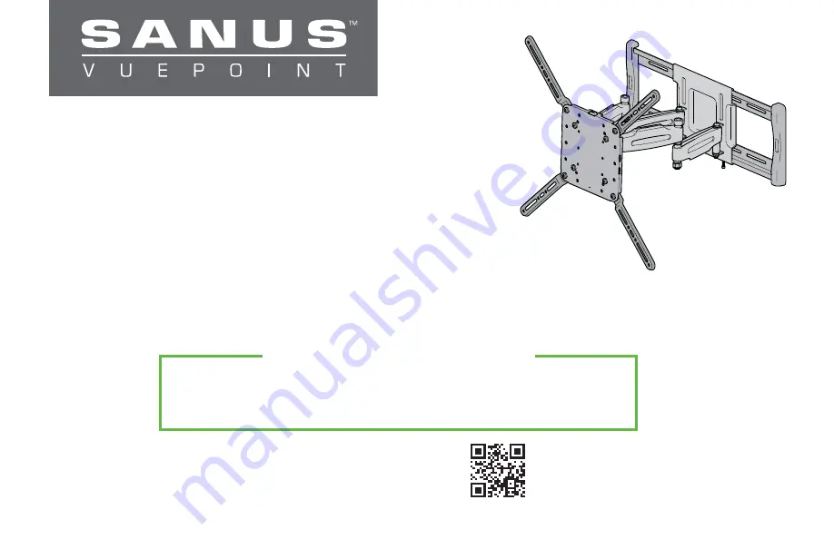
INSTRUCTION MANUAL
Scan for easy install video
san.us/54
We’ll Make It Stress-Free
If you have any questions along the way, just give us a call.
1-888-333-9952. We’re ready to help!
Page 1: ...FLF118 INSTRUCTION MANUAL Scan for easy install video san us 54 We ll Make It Stress Free If you have any questions along the way just give us a call 1 888 333 9952 We re ready to help...
Page 2: ...of this product contact Customer Service at 1 888 333 9952 CAUTION Avoid potential personal injuries and property damage This product is designed for use in wood stud solid concrete and concrete bloc...
Page 3: ...35in 549 9mm 21 65in 680 9mm 26 81in 100mm 3 94in 200mm 7 87in 400mm 15 75in 600mm 23 62in 463 8mm 18 26in 12deg 5deg 31deg 31deg ESTIMATED SWIVEL BASED ON A 55 TV TV INTERFACE WALL PLATE FULLY ASSEM...
Page 4: ...tarting assembly verify all parts are included and undamaged If any parts are missing or damaged do not return the damaged item to your dealer contact Customer Service Never use damaged parts Supplied...
Page 5: ...inches inch dimensions are approximate Measure the width and height of your TV hole pattern in cm Record your measurements Width ________cm X Height ________cm 75 mm 7 5 cm 3 in 100 mm 10 cm 4 in 200...
Page 6: ...20 0 7 87 20 0 3 94 10 0 3 94 10 0 15 75 40 0 15 75 40 0 in cm in cm Assemble TV bracket extenders 02 onto TV bracket 01 as illustrated Secure using eight screws 03 in the corner holes shown 03 02 02...
Page 7: ...ght screws 03 in the corner holes shown 60 0 x 40 0 03 Assemble TV bracket extenders 02 onto TV bracket 01 as illustrated Secure using eight screws 03 in the corner holes shown 02 02 15 75 40 0 15 75...
Page 8: ...rter screws Spacers and longer screws are supplied to accommodate Round irregular back TVs TVs with inset mounting holes Extra space needed for cables Too Long Too Short Correct Standard configuration...
Page 9: ...Position your TV bracket configuration A B C or D over your TV hole pattern making sure the bracket is centered over the TV hole pattern and level Secure bracket using your screw washer Flat Back or s...
Page 10: ...ference the product manual for details on mounting to concrete Be sure to review the manual for complete safety instructions MODEL FLF118 6700 004791 00 san us 1093 40 60 in 101 152 cm 10 10 From your...
Page 11: ...11 STEP 2 1 Assemble Your Wall Plate 12 12 13 13 8 mm wrench...
Page 12: ...4 in 51 x 102 mm nominal 1 x 3 in 38 x 89 mm Minimum horizontal space between fasteners 16 in 406 mm 1 Locate your stud Verify and mark the center of the stud by nding the stud edges using an awl a t...
Page 13: ...of 3 in 89 mm 4 Install wall plate assembly using four lag bolts 14 Tighten the lag bolts 14 only until they are pulled firmly against the wall plate assembly CAUTION Avoid potential personal injury o...
Page 14: ...on the wall at your desired height Level the wall plate template and mark the hole locations 2 Drill three pilot holes using a 3 8 in 10 mm diameter masonry drill bit IMPORTANT Pilot holes must be dr...
Page 15: ...e lag bolts and washers from the Concrete Installation Kit CMK1 Tighten the lag bolts C1 only until they are pulled firmly against the wall plate assembly CAUTION Improper use could reduce the holding...
Page 16: ...TEP 3 Parts and Hardware WARNING This product containssmallitemsthatcouldbe a choking hazard if swallowed STEP 3 Attach Arm to Wall Plate HEAVY You may need assistance with this step 1 Hang the arm 15...
Page 17: ...mm hex key 17 to secure arm to wall plate assembly CAUTION Avoid potential injury or property damage M5 wall plate screws 16 must be installed to secure the arm 15 to the wall plate assembly 15 15 16...
Page 18: ...step M5 x 6 mm STEP 4 Hardware WARNING This product contains small items that could be a choking hazard if swallowed Before starting assembly verify all parts are included and undamaged If any parts a...
Page 19: ...he top and bottom of the arm 15 2 Using the 4mm hex key 17 secure the TV bracket 01 to the arm 15 with screw 19 and washer 20 CAUTION Avoid potential injury or property damage This screw 19 must be in...
Page 20: ...f swallowed Before starting assembly verify all parts are included and undamaged If any parts are missing or damaged do not return the damaged item to your dealer contact Customer Service Never use da...