F107d
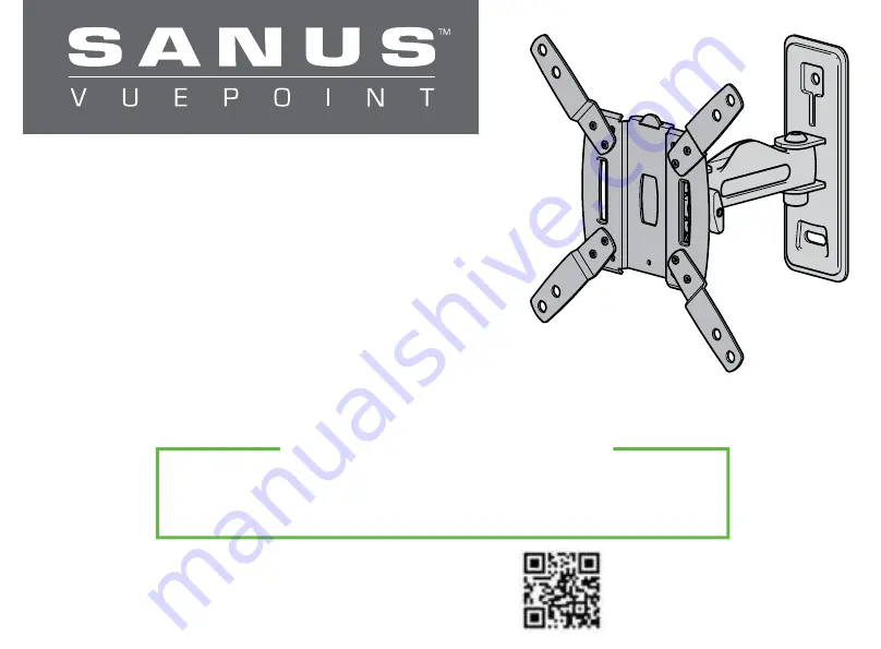
INSTRUCTION MANUAL
Scan for easy install video
san.us/793
We’ll Make It Stress-Free
If you have any questions along the way, just give us a call.
1-888-333-9952. We’re ready to help!
Page 1: ...F107d INSTRUCTION MANUAL Scan for easy install video san us 793 We ll Make It Stress Free If you have any questions along the way just give us a call 1 888 333 9952 We re ready to help...
Page 2: ...ll process Also check your TV owner s manual to see if there are any special requirements for mounting your TV If you do not understand these instructions or have doubts about the safety of the instal...
Page 3: ...0 7 9 20 0 7 6 19 3 2 9 7 5 7 2 18 3 4 3 10 8 7 9 20 0 3 9 10 0 3 9 10 0 3 0 7 5 16 16 3 0 7 5 2 6 6 5 NOTE TV shifts 4 3 in 10 8 cm to the right or left when in the home position Consider this when s...
Page 4: ...NOTE Not all hardware included will be used WARNING This product contains small items that could be a choking hazard if swallowed Before starting assembly verify all parts are included and undamaged...
Page 5: ...ate Lag Bolts Washer Cable Ties Locking Screw 5 16 x 2 in 695 x 350 x 075 in Concrete Installation Kit CMK1 not included x4 x4 x4 695 x 350 x 075 in 5 16 x 2 in Contact Customer Service at 1 888 333 9...
Page 6: ...1 1 Measure Your TV Hole Pattern 1 2 Assemble Your TV Bracket Determine which TV bracket configuration to use A B or C based on your TV hole pattern measurements cm inches 02 03 inch dimensions are ap...
Page 7: ...ted Secure using eight screws 03 in the corner holes shown B C 20 0 x 20 0 01 20 0 20 0 02 02 02 02 03 Assemble TV bracket extenders 02 onto TV bracket 01 as illustrated Secure using eight screws 03 i...
Page 8: ...f you are uncertain about your hardware selection contact Customer Service at 1 888 333 9952 M5 M6 FLAT BACK ROUND BACK CABLES INSET HOLES M4 If your TV has a flat back AND you want your TV closer to...
Page 9: ...er Round Back Extra Space selection IMPORTANT Ensure TV bracket is securely fastened before moving on to the next step 12 02 01 TV Bracket Con guration A Illustrated with spacers TV Bracket Con gurati...
Page 10: ...ud size common 2 x 4 in 51 x 102 mm nominal 1 x 3 in 38 x 89 mm 1 Locate your stud Verify and mark the center of the stud by finding the stud edges using an awl a thin nail or an edge to edge stud fin...
Page 11: ...he wall plate CAUTION Improper use could reduce the holding power of the lag bolt DO NOT over tighten the lag bolts NOTE If needed you can make small level adjustments to the wall plate by loosening t...
Page 12: ...Level the wall plate template and mark the hole locations 2 Drill two pilot holes using a 3 8 in 10 mm diameter masonry drill bit IMPORTANT Pilot holes must be drilled to a depth of 3 in 75 mm Never...
Page 13: ...stallation Kit CMK1 Tighten the lag bolts only until they are pulled firmly against the wall plate CAUTION Improper use could reduce the holding power of the lag bolt DO NOT over tighten the lag bolts...
Page 14: ...to the arm of wall plate assembly 14 by first hooking the top support then resting the TV into place 2 Lock the TV to the wall plate assembly 14 with locking screw 16 and washer 17 IMPORTANT This lock...
Page 15: ...15 Manage Cables Cables can be routed through the cable channel on the top of the arm of the wall plate assembly 14 for a cleaner look 14 18...
Page 16: ...TE Once your TV is in place tighten the tilt tension knob to prevent unwanted movement LEVEL ADJUSTMENT To adjust the leveling of your TV loosen the locking screw 16 level your TV then tighten locking...
Page 17: ...17 REMOVING THE TV To remove your TV from the wall plate assembly 14 disconnect all cables and then reverse the procedures in STEP 3 14 HEAVY You may need assistance with this step...
Page 18: ...18 Features 20 0 20 0 10 0 7 5 10 0 7 5 TV bracket can be con gured to t TV hole patterns from 7 5 x 7 5 cm up to 20 0 x 20 0 cm...
Page 19: ...lly articulating arm creates 2 point movement for optimal viewing position Cable channel holds cables along mount arm for a clean look Adjustments allow ngertip control of TV or restriction of TV move...
Page 20: ...del uso del producto cont ctese con el servicio de atenci n al cliente al 1 888 333 9952 Antes de comenzar verifiquemos que este soporte sea perfecto para usted 1 2 3 4 PRECAUCI N Evite lesiones y da...
Page 21: ...configuraci n de placa de sujeci n debe usar A B o C seg n las medidas del patr n de orificios del televisor Los patrones de orificios m s peque os solo requieren placa de sujeci n 01 No utilice las...
Page 22: ...verifique que est centrada y nivelada verticalmente Instale las placas de sujeci n usando la combinaci n que haya seleccionado para su televisor tornillo corto y arandela o espaciador o bien tornillo...
Page 23: ...debido podr a reducir la capacidad de retenci n de los tornillos NO ajuste en exceso los tornillos tirafondo Comun quese con el servicio de atenci n al cliente al 1 888 333 9952 para solicitar que le...
Page 24: ...los cables del televisor a lo largo del brazo para dar un aspecto m s prolijo 1 Para colgar el televisor en el brazo del m dulo de la placa mural 14 primero enganche el soporte superior y luego apoye...
Page 25: ...para evitar movimientos indeseados AJUSTE DEL NIVEL Para ajustar la nivelaci n de su televisor afloje el tornillo de seguridad 16 nivele el televisor y luego ajuste el tornillo de seguridad 16 IMPORT...
Page 26: ...nte articulado crea un movimiento de 2 puntos para alcanzar una posici n de visualizaci n ptima Los canales para cables sujetan los cables a lo largo del brazo para un aspecto prolijo Los ajustes perm...
Page 27: ...27...
Page 28: ...y kind Milestone makes no representation of warranty expressed or implied regarding the information contained herein Milestone assumes no responsibility for accuracy completeness or sufficiency of the...