Installer’s Preoperational Check
THE FOLLOWING ITEMS MUST BE PERFORMED BEFORE ATTEMPTING TO OPERATE THE EQUIPMENT:
INSTALLERS PREOPERATIONAL CHECK
PAGE 2
Make certain that proper electrical connections have been
made. Plug power cord into power outlet.
WARNING
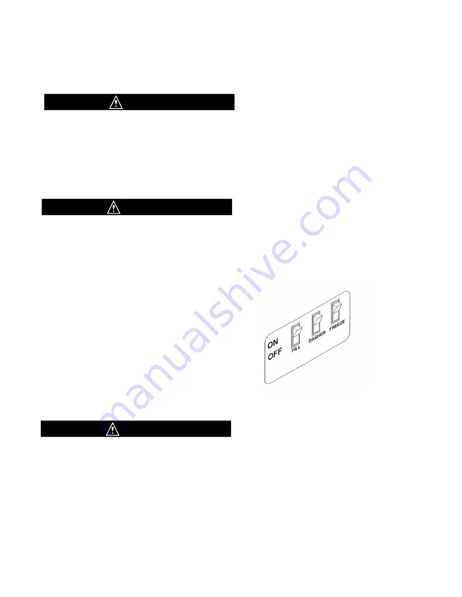
Fig. 3
Control Switch
UNDER NO CIRCUMSTANCES SHOULD THE UNIT
BE OPERATED WITH THE FREEZE AND DASHER
SWITCH (Fig. 2) ON FOR MORE THAN THREE
MINUTES WITH EMPTY FREEZING CYLINDERS .
DOING SO WILL RESULT IN DAMAGE TO THE
MACHINE.
1. Position the dispensing head, autofill system and the
condensing unit in the appropriate locations.
2. Cord connect as follows:
Dispensing Head -12-3 electrical cord
120V 15 amp service
3. Install precharged refrigeration copper lines from the
dispensing head to the condensing unit. The copper tubes
are soldered into the supplied quick connect / disconnect
fittings, a 3/8” non-insulated copper for discharge (high
side) and 5/8” insulated copper for the low side (suction).
FAILURE TO PROVIDE FOR PROPER EARTH GROUD
ACCORDING TO APPLICABLE ELECTRICAL CODES
COULD RESULT IN SERIOUS ELECTRICAL SHOCK.
CAUTION
CAUTION
4. A 3/8” barbed fitting is available on the back of the
dispensing head for easy autofill installation. The prod-
uct supple line should have the most pressure to the
pan and not splash. Max pressure is 75 psi.
5. Install and activate the autofill systems to fill and
satisfy the probes. The purge button on the faceplate
must be depressed to relieve as much air from the sys-
tem as possible. This is only required during initial
filling or after cleaning.


