SANI Membranes Vibro-I 2 Series Manual Download Page 19


19 

Version: 20221219 

B.


Permeate system 

The manifold is designed to avoid negative 

transmembrane pressure (TMP) as this can cause 

damage to the membrane modules. A negative TMP can 

occur when reducing the feed pressure dramatically or 

stopping the feed system quickly.  

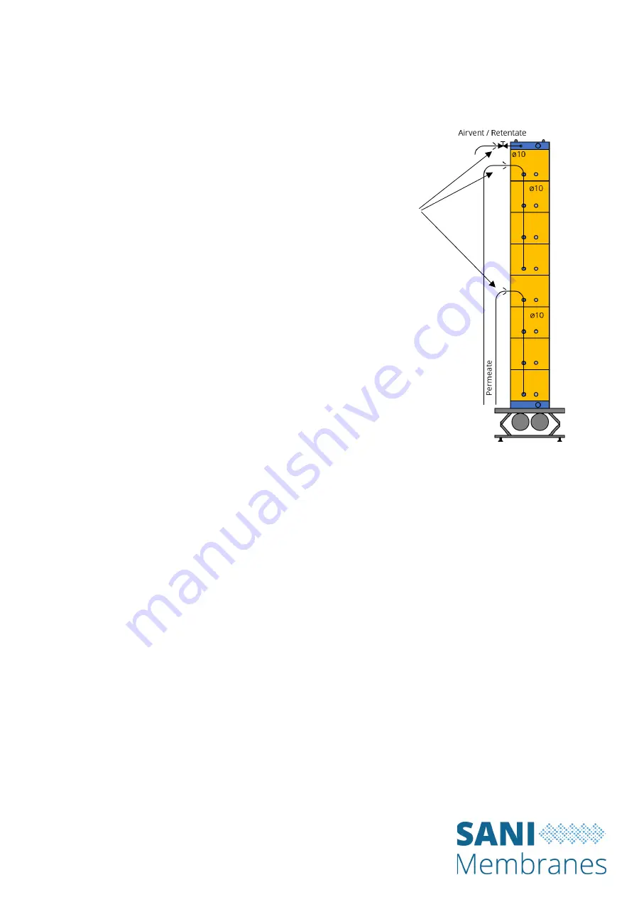
In microfiltration applications it is often key to have a 

low, uniform TMP. To facilitate this the manifold for 

microfiltration systems leads the permeate up along the 

modules, as shown in the illustration to the right. To 

enable drainage of the permeate side a drain valve can 

be included at the bottom of the permeate manifold. 

The permeate rate may be controlled by using a positive 

displacement type pump on the permeate line. This will 

restrict the permeate flow and will enable unique process control at low uniform TMP during 

microfiltration. Read more about this in Section E below (

Examples of membrane filtration 

process configurations

). 

For ultrafiltration applications the pressure conditions are less critical and the manifold can 

instead be designed to lead the permeate down along the modules. A vent valve can 

optionally be included at the top of the manifold to assist draining of the permeate side. 

In general it is recommended to reduce the pressure drop in the permeate system by using a 

larger diameter tubing between the Vibro-I and the collection tank.


Avoid 
pressure 
drop using 
larger 
diameter 
tubing to 
the 
collection 
tank 

Summary of Contents for Vibro-I 2 Series

Page 1: ...ead this entire user manual prior to use of the equipment Please read all safety instructions carefully This user manual is part of the product Keep it in a safe place for future reference Replacement...

Page 2: ...fication 14 C Media 14 D Pressurized components 15 E Leaking fluids 16 F Moving parts 16 G Personal protective equipment 16 H Accessories and spare parts 17 5 Operation 18 A Introduction 18 B Permeate...

Page 3: ...rage of used HP1 membrane modules 32 7 Service and maintenance 33 A Tightening and re tightening the Vibro I top bolts 33 B Inspection of the Vibro I cushion assemblies 33 C Exchanging or re inflating...

Page 4: ...f media and membrane creates turbulence on the membrane surface and thereby keeps the fouling layer at a minimum The turbulence is only created at vertical surfaces Thus the energy required to create...

Page 5: ...r industrial membrane system The Vibro I is fully drainable of both retentate and permeate resulting in minimal product loss and faster CIP cycles The Vibro I range is a modular design based on the 2...

Page 6: ...covering Vibro I 7 5 20 m Series 1 Designed for vertical installation of 3 4 6 or 8 HP1 modules resulting in membrane areas of 7 5 m 10 m 15 m and 20 m Vibro I 2 5 and 5 m Series 1 Designed for horizo...

Page 7: ...NING This symbol denotes a possible danger with medium risk that death or severe injury may result if it is not avoided CAUTION This symbol denotes a possible danger with a low risk that moderate or m...

Page 8: ...bro I drive frame 1 Each cartridge includes a permeate manifold system 3 For the Vibro I 10 or 20 m units one cartridge with 4 or 8 HP1 modules respectively is mounted on the Vibro I drive frame For t...

Page 9: ...e s are fixed to the base plate using four bolts for each cartridge The Vibro I stand 8 is designed for permeanent installation in the shop floor or on a larger support structure Foundation plan for e...

Page 10: ...ts of a number of stacked HP1 2 5 m membrane modules 9 assembled with a cushion assembly 11 at the top and at the bottom of the HP1 stack An internal square o ring 10 seals between the assembly parts...

Page 11: ...top of the manifold and the blind plug at the bottom This configuration helps to ensure that the transmembrane pressure is uniform throughout the entire membrane area For ultrafiltration it is not as...

Page 12: ...0 m units The 40 and 80 m units may also include liquid manifolds for the feed and retentate lines These are to be connected by flexible hoses to the feed retentate system Below are shown two examples...

Page 13: ...ANI Membranes The Vibro I can only be used together with a feed system with a built in safety to protect the Vibro I against over pressure If the feed system is able to deliver over pressure a CE appr...

Page 14: ...materials in Safety Classes 2 and 3 Use of flammable or potentially explosive substances Filtration of unstable media Use of media which are incompatible with PP Stainless Steel Silicone EPDM or othe...

Page 15: ...ke sure that the media to be filtered is compatible with the materials in fluid connection in the Vibro I PP Stainless Steel and silicone and the feed system used ATTENTION D Pressurized components Th...

Page 16: ...moving parts e g the membrane assembly the industrial springs This can lead to injuries WARNING Lose hair or lose clothing parts can be caught in moving parts and cause injuries CAUTION The Vibro I mu...

Page 17: ...y valve set according to the section D Pressurized Components above WARNING The use of unsuitable accessories consumables and spare parts can be hazardous and have the following consequences Severe pe...

Page 18: ...etween the vibrating equipment and static equipment such as feed pump permeate tank and retentate tank must be done with flexible tubing or hoses In order to reduce the tranfer of vibrations the conne...

Page 19: ...e rate may be controlled by using a positive displacement type pump on the permeate line This will restrict the permeate flow and will enable unique process control at low uniform TMP during microfilt...

Page 20: ...perations with respect to these limits During filling and draining the individual Vibro I may be vented to avoid over under pressure inside the membrane assembly The Vibro I motors must be turned off...

Page 21: ...rane This value can be used throughout the lifetime of the membrane as a benchmark for the efficiency of the CIP regime after each production The clean water flux should be measured at a set of standa...

Page 22: ...sure 0 1 bar Keeping a very low trans membrane pressure between 0 05 to 0 25 bar often gives the best long time results The optimum is membrane and product dependent The initial flux can be very high...

Page 23: ...ated from the amount of permeate collected and the initial feed volume This setup can also be used for diafiltration applications Microfiltration mode with permeate flow control pump Unique process co...

Page 24: ...s coupled in parallel and or in series The optimal process design will always be product and scale dependent A simple example of a more complex configuration is provided below It includes a two stage...

Page 25: ...ration The following procedure is a general guideline applicable for the cleaning of the Vibro I The individual process and product may require a different approach to achieve satisfactory cleaning re...

Page 26: ...r flux After cleaning the membrane the clean water flux should be measured By comparing the clean water flux after each cleaning cycle with the original membrane performance it is possible to determin...

Page 27: ...H 20 ethanol 20 isopropanol Always seek the applicable safety information for the selected checmicals used as storage solution e g handling and storage and conduct in emergency situations For long ter...

Page 28: ...s for the 40 m and 80 m units are kept in position at the top with a stainless steel top ring The top ring has 8 holes that fit over two of the rods from each cartridge like shown in the illustration...

Page 29: ...each membrane assembly 4 Remove the top Vibro I cushion assembly 2 5 Remove the inner gasket 3 from the top HP1 module 1 6 Remove the HP1 modules 1 one by one and remove the inner gasket 3 from each m...

Page 30: ...Make sure that the lip of the inner gasket is facing up 4 Place the first HP1 module 1 in the desired orientation by sliding it over the rods 5 and ensure it is perfectly aligned with the Vibro I cus...

Page 31: ...ine on the HP1 module Please see below illustrations Correct alignment of the cushion assembly and the HP1 module 9 Place a washer on each rod 5 and secure the nuts 6 by cross tightening them slowly w...

Page 32: ...tion that also prevent bacterial growth The HP1 module can be placed in suitable containers such as a large plastic bucket with lid Make sure that the entire module is submerged in the storage solutio...

Page 33: ...nit is vibrating B Inspection of the Vibro I cushion assemblies The cushion assembly is a wear part that should be inspected regularly Through regular operation the cushions may gradually deflate and...

Page 34: ...holes corresponding to the threads in the top bottom part The middle hole along each side is not used 7 Place the inlet part on top of the top bottom part while aligning the 4 unused holes 8 Cross ti...

Page 35: ...4 Run a test production on the unit to analyze permeate samples from each HP1 module The test setup could be like shown in the below illustration 5 Mark the HP1 module s with unacceptable permeate qu...

Page 36: ...he production E Flux performance If the clean water flux performance of the plant drops the cleaning regime may be inadequate for the specific product and process Consult a qualified chemicals supplie...

Page 37: ...d lifetime of the wheels is around 1000 hours of operation but the actual lifetime will dependent on conditions such as the floor surface finish for instance G Maintenance and exchange of the industri...

Page 38: ...80 C Vibration Motor 400VAC 50Hz 3 200 W Vibro I 80 m2 Weight 660 815 kg drained full Dimensions L x W x H 1000 mm x 860 mm x 2660 mm Membrane 32 x 2 5 m2 Free Flow Plate Modules HP1 Internal Retenta...

Page 39: ...CE marked to demonstrate compliance with relevant regulations including the European Machine Electrical and Pressure Directives The Vibro I can conform to GMP FDA EC regulations for materials in cont...

Reviews: